DuiBot1(8servo) && RYU(12servo)

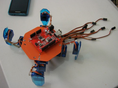
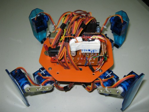
Ok. This is an upgrade(control) for my 8 servo 4 legged walker... now its using an arduino328 clone. Currently, its still remote controlled via hacked cheap R/C car rx/tx electronics... more to add: if remote control is not used, will go to autonomous mode, using either IR sensor or ultrasound sensor.

currently, it only has 2 walking gaits (im still researching) and finding a *cool* walking gait :)


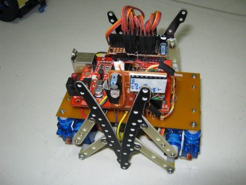
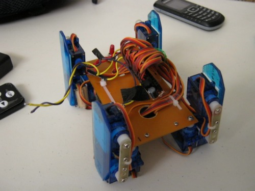
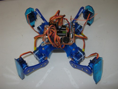
here it is shown, rest mode... RF reciever clearly shown.

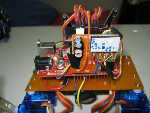
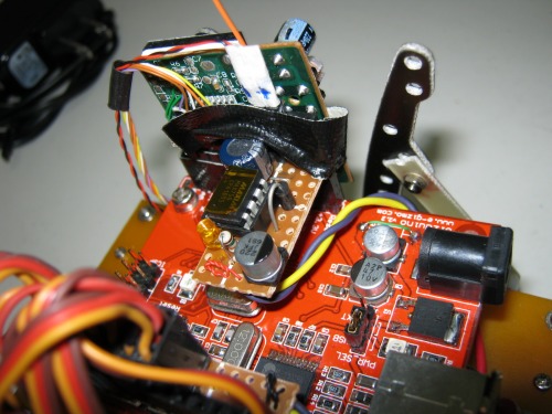
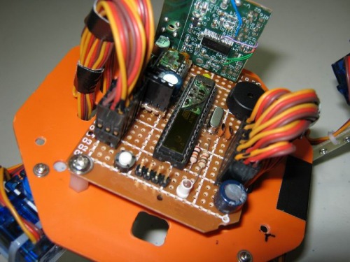
here is a clearer shot of the RF receiver

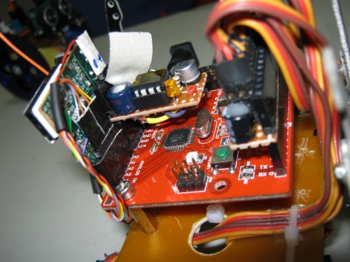
the connections to the arduino, the tiny board next to it, the DC-DC aka mintyboost :) to power the arduino board (5V)...sorry the RF receiver is only taped. hehe

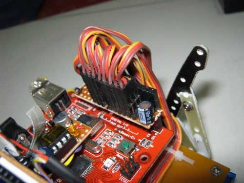
now for the servo connections, had to cut out a protoPCB strip..

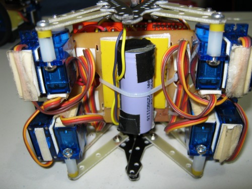
now, the power source..3.6V 1300mA Li-ion Battery..

another view at the DC-DC power supply.. had to REALLY make sure it worked.. power goes directly to the 5V supply lines of the duino board, bypassing the 5V regulator! XD

more work (and coding) needs to be done here... the RF remote has 5 channels in it..Im still thinking WHAT to do with the last one, since its not being used .... maybe if I press that, it will do a DEMO mode..  another thing in my mind, if not remote controlled, will enter autonomous mode and walk forward/avoid obstacles.. but im still thinking what sensor to use here... :)


video... just a short teaser.. more to come eventually.... goodnight everyone(its about 10pm here)

=================2nd UPDATE MARCH 08,2012============================================

RECENT GOAL: program a *cool* walking gait

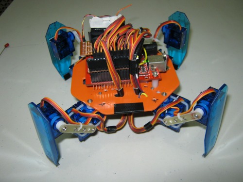
NEW GOAL: convert this 8 servo walker to a 12 servo

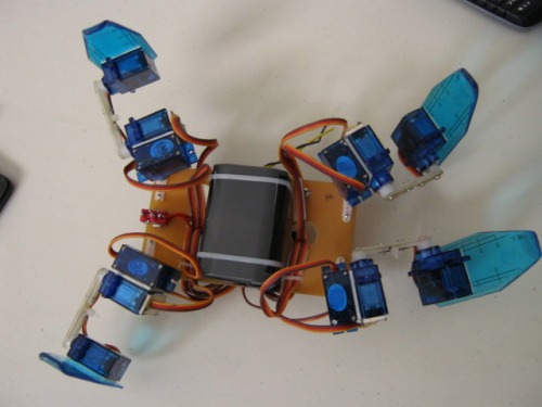
well... I have here a bunch of scrap "legs" from an existing dismantled 6 legged walker (18 servos), given by a store owner who also laser-cuts acrylic plastic sheets.. so I used them temporarily, to see if my -idea- both hardware & software works, AND IT DID! yay! :D ..... check out the 2nd video.. currently, the remaining 3 legs are "detached" at the moment... though seeing it move, seems like there is JUST? a little difference (walking = mechanically) as compared to using 8 servos... hmmmmm and hmmmmmmm

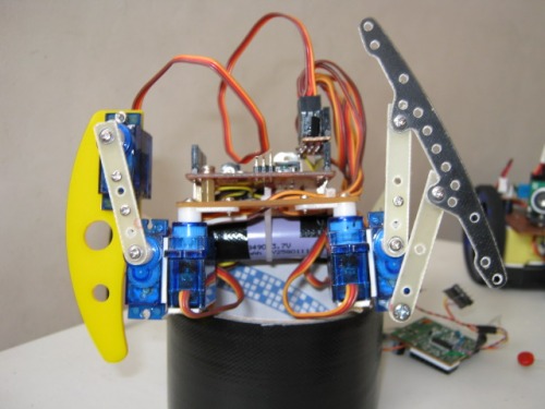
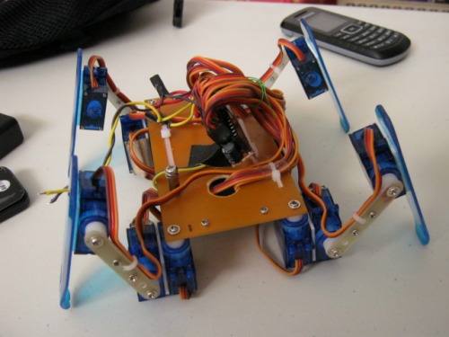
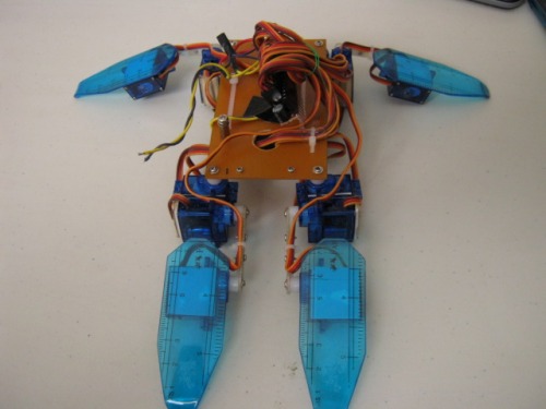
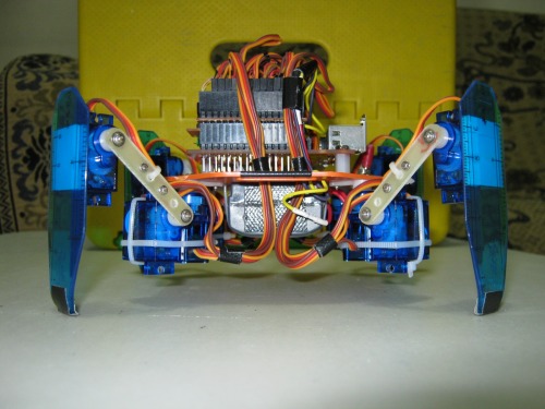
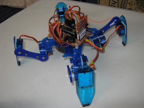
OK..here shown when legs are folded... better position than the other one..big difference (I admit)

Folded nice

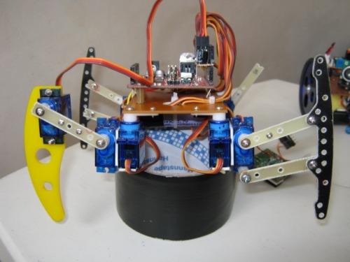
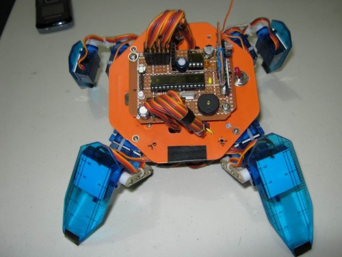
and HERE, in its normal walking position.. not much of a difference as compared to the other, eh?

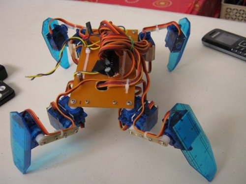
BUT.. can it do THIS? leg stretching? I dont think so.. LOL XD (hey no offense to the 8 servo walkers out there) :) so this is what makes the big difference (and more power too from battery) .....

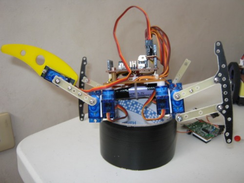
again, till next time! :=)


==========================3rd UPDATE===============whew :) =====================

I need MORE CURRENT from the battery..so added another one.. so that means bot is much heavier than before.. PLUS the additional 4 servos.. woooo

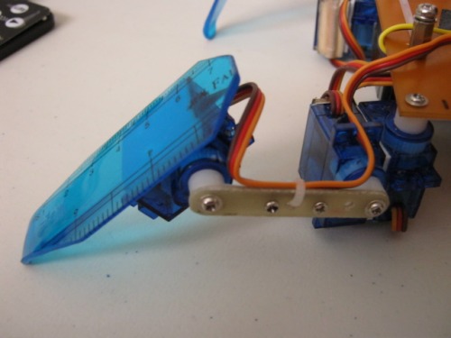
close up view of the leg... yup its a plastic rule :=D .... liked the color! lol.. back supports? hmm maybe next time..


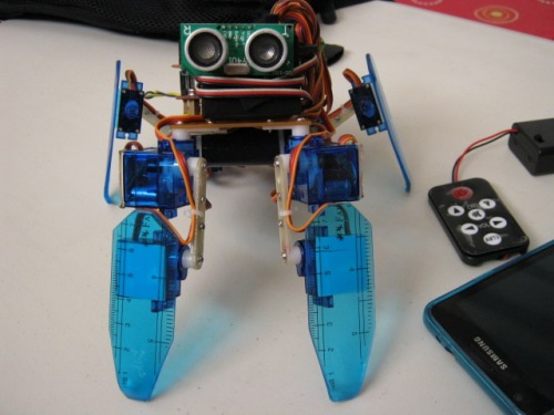
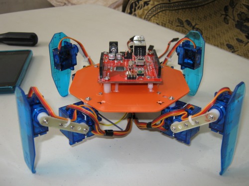
here he is, sitting.. and a mock-up of its head(sonar + servo)... :)

and yes its walking already (running actually).. I had to remove the duino board so I could add some more *gimmik* stuff.. sound/remote/sensors etc... so again, stay tuned !

==============UPDATE APR 11 , 2012===== new hardware=========================

ok, new chassis.. its from an electric ulitity box cover... this makes the weight distribution more balanced...

ok folks.. thats all for now :) cheers!

==================UPDATE UPDATE UPDATE :D ============================================

Ok I now name IT "RYU"... thats final :-)  bye duiBOT :_(

here shown the RF "module" taken from a cheap R/C toy...

ihow high it is, relative to ground...I like it low profile... :)

I really like this configuration... it can go (N)orth (E)ast (W)est (S)outh and rotate...

check out the video(WILL UPLOAD LATER).. its finally UP..whew :)

==========small update===========================APR 15==================================

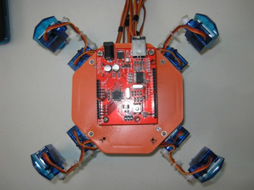
removed the arduino clone board, bought a blank 328-PU, bootlloaded it and made a new board just for this walker...

the "programming pins" shown.. +5/Tx/Rx/GND(dot)....next update, replace the ORANGE chassis.. :D

======UPDATE UPDATE UPDATE april 20, 2012============================================

ok, just some minor mechanical updates.. made the legs a bit longer.. using blue acrylic plastic.. and changed the base color also to blue... :)

next update, maybe this will be an autonomous one, remove the remote control and add sensor switches at the feet + accellerometer, so that body will be parallel to ground.... :)

--------update april 21, 2012-------------

just a minor update.. I got me here a master/slave UART BT..just did some "echo" tests using virtual com port,and its all good :) *will* replace the RF module im currently using, so this means I could free up some more I/O pins..

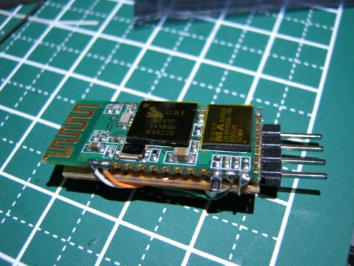
Im using a breadboarded atmega328 duino, so Im planning to "tap" on the rx/tx pins, only other thing is, when I upload a sketch, I have to remove this module :).. and with this setup, I think I could use the PC virtual terminal as my remote control for this bot...have not done this yet, its still in my mind atm :D  next path: move on to using an android phone as my controller :) <next for learning, making android app>

4 legged, can be remote controlled or autonomous

  • Actuators / output devices: 8pcs 9g servos
  • Control method: RF remote / autonomous
  • Power source: 3.6V Li-Ion
  • Programming language: Arduino C
  • Sensors / input devices: none at the moment
  • Target environment: indoors mainly

This is a companion discussion topic for the original entry at https://community.robotshop.com/robots/show/duibot1-8servo-ryu-12servo

NICE!!!

NICE!!!

How rude! :stuck_out_tongue:

Teasing us like that. lol

Nice bot. With your arduino clone you should have a whole slew of I/O. You wouldn’t be limited to only one sensor. Heck, you could have a touch sensor on each foot. You could check the angle of any or all of the servos. Don’t limit yourself. :slight_smile:

lol :smiley: thanks!

yeah. endless possibility there :slight_smile: I really am liking this arduino stuff… much easier to do codes (especially with those sensors needing timer1 stuff etc etc) … really had a hard time doing THIS on HT C (no offense) hehe

anyways, at this rate im kinda running low on IOs…already  8 for the servos +  5 for the remote function… just a few more to go .maybe another servo for panning and a couple more for the ultrasound. but hey, its my first time to use this extensively :smiley:

sorry for the teaser part XD .current Code/hw does forward<gait1>/backward<gait2>/rotate left/rotate right… BUT I was already very sleepy that time, had to do a quick video upload… till next time :slight_smile:

thank you / salamat :slight_smile:

thank you / salamat :slight_smile:

I’m a bit confused.

From the Atmel website the 328 has a max of 23 available I/O pins. You are only using 13 pins. You should have at most 10 more pins available. Unless, your clone board doesn’t bring out all of the available I/O pins.

Arduino has 20 pins

Arduino has 20 pins available for the user (14 digital plus 6 analog). If you use an internal clock you free up 2 more pins and if you turn the Reset pin into a I/O pin you get to the maximum of 23 pins as per Atmel website. But I suggest you stick with the stock options here. Many people do not use the Tx and Rx pins for anything since they need those pins to upload the code to the Arduino, so they can use 18 pins, that’s 5 more pins still available for the extra stuff.

Thanks for the education. :slight_smile:

I figured the 23 pin max included some pins that are typically used by other standard arduino hardware.

hmmm

That I did not know of… Im still a n00b at this arduino stuff & picaxe too (started just this month actually)… anyways, I think i will just stick with the “standard” way of using an arduino… lol :smiley: yeah got the point, thanks.

I was also thinking of using a “barebones” kind of thing… If I could find a DIP atmega328, then ill have it bootloaded(duino) then use a usb-serial cable to upload codes from the arduino IDE.

that said and done, im still experimenting on how this bot would “WALK” the walk, like NOT -robotic- lol.dont know the term for that. :D 

ok got it… will look into

ok got it… will look into it now :slight_smile: thanks

duino mapping


I have been looking at this:

http://arduino.cc/en/Hacking/PinMapping168

said the SMD version has extra ADC lines versus the PDIP version… and here is a picture of my board (gizduino)…yes, those pads labeled A6 and A7 have connections to the chip(328P), but if you look at the other side, the “digitalpin” ends at #19… I have a question, since its labeled as A6 and A7(but no terminals yet), I assume I could use them for analog, right?  how about digital I/O? if so, then perhaps digital I/O # 20 and 21? thanks

IMG_0445.jpg

I should have been g00gling more . lol

here is the answer to my question:

http://arduino.cc/forum/index.php?topic=89342.0

so, its only an extra analog input.. can NOT be used as OUTPUT.. cool... :)


another Hmmmmmm (idea in my

another Hmmmmmm (idea in my mind)

I could try making THIS into a 12 servo walker(3 servos per leg)… but then… comes the “ruining” of CODE… lol… arggg… but I could make a function w/c will just call a single command for the knee+feet servo/s… so a call of “lift” will lift the knee servo && counter-rotate the feet servo… :smiley: anywho maybe next time…

Your robot is really cool.

You inspired me with your spacers!

But now i’m like you I want a 3 DOF per leg robot… so much GAIT available then.

I have a question: What kind of material do you use to stick the 2 servos together? double-tape?

And what is the material you use for the legs? (it looks like PCB…) And for the chassis?

You are getting weight issues, commun problem with legged robots

Keep up the good work :slight_smile:

Hi

   I use 3M double sided “permanent” tape to stick the 2 servos together…material for legs? yup PCB… FR4 material (fiber)… chassis? its PCB also but PP material only… weight issues is just normal …its now a 3 DOF per leg robot walker… 12 servo :slight_smile: check out my 3 video… currently, its AGAIN dismantled… having some balancing issue with the current chassis so im changing it now…check out my latest pics.

Your bot

is coming along very nicely. Your videos aren’t so much of a tease anymore either. :smiley: Keep up the work and thanks for keeping us updated.

HI

Hi I’m new to LMR, how would you go by making it autnomous and controlled? For school we have a project that gives us 6 months, to build animal robot, I’m thinking of making a dog that walks and has distance sensors, so it doesn’t collide into walls Etc, what do you think? any animals you could suggest I make, because I hae no idea, what to make :frowning:


thanks :slight_smile:

Hi


 For a school project, if budget is of little or no concern, you could make it a quadroped (4 legs) using servos…just like what I did… or if it feels a bit intimidating, how about making a “wheeled” animal :slight_smile: like a ladybug or somthing… just hide the wheels underneath the chassis…

:slight_smile:

Thanks for the idea, I’m thinking of making quadroped, the school budjet is pretty good and we’re allowed to fund ourselves if we like, so I will do that, as I would like to spend my money on things that I like :slight_smile: I was thinking about doind like a kangaroo with wheels covering it, but I though the quadroped would be more exciting and challenging and since we have 6 months to build, maybe for you ,you could do it fast, our class is fairly new at this .

Awesome

Extremely awesome bot you’ve built in the end and you’ve given me ideas. It looks like I too will shift to a crab instead of a 2 wheel rover. :wink: congratulations once again.

hey

thanks. :slight_smile: