BRC Beginners robot chassis

This is BRC, a line following and obstacles avoiding robot made for the Beginners robot chassis challenge.


Parts used:

* 1x DAGU Beginners robot chassis.

* 1x Arduino duemilanove

* 1x Arduino proto shield

* 1x L293D motor drive chip

* 1x 9V battery

* 1x 3 AA batter pack and 3 AA batteries (I found a good spot under the chassis to hold

the battery pack)

* 1x Micro servo

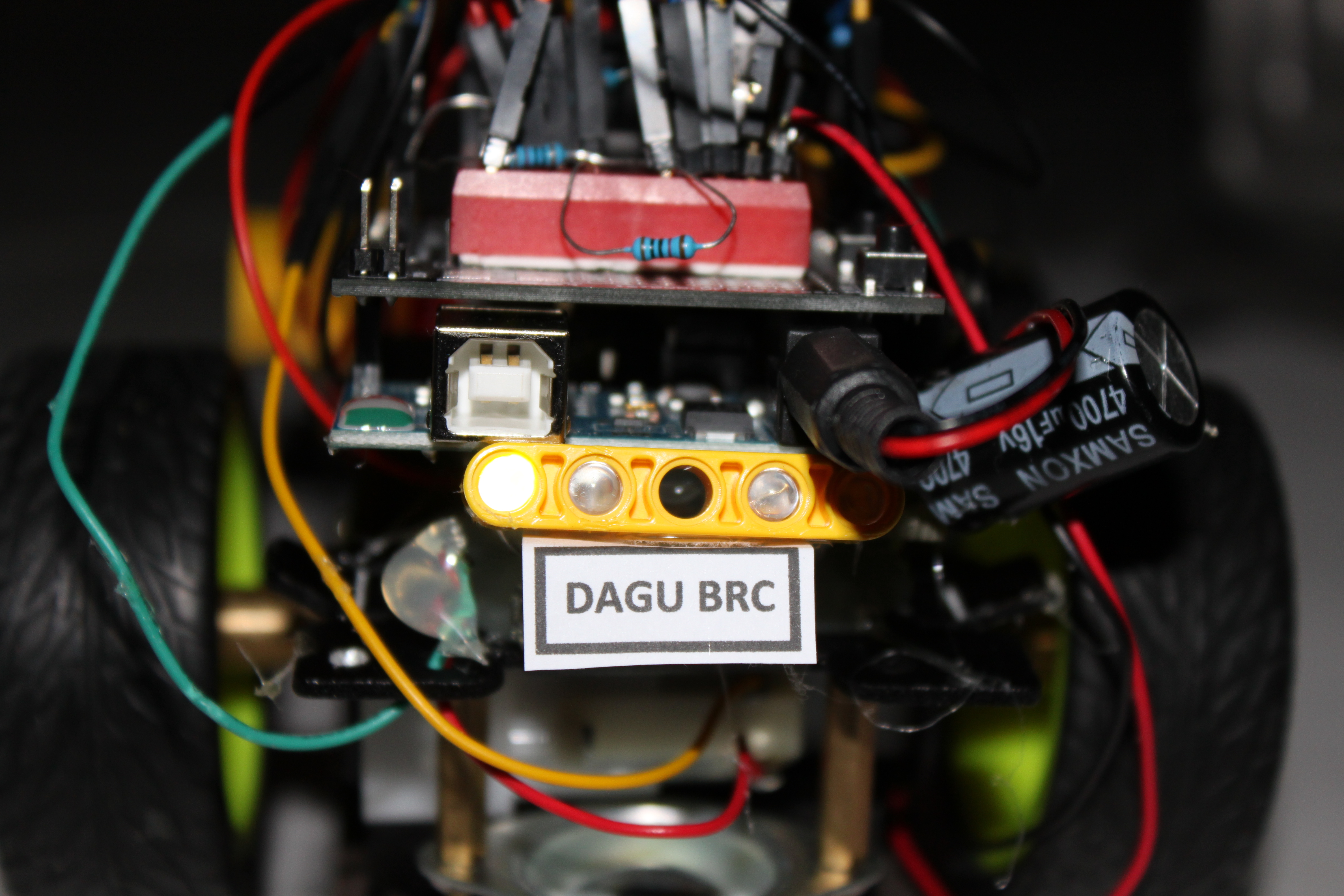
* 5x Pololu Sharp IR Distance Sensor GP2Y0D810Z0F (these sensors are super awesome for line following, they give a reading above 800 on any dark black object. In this case its the black tape)

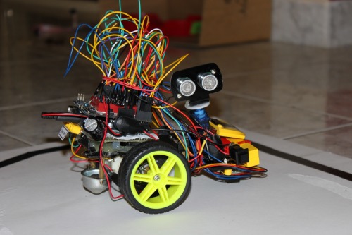
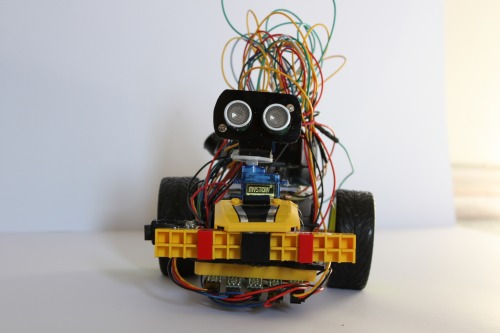
* and lastly, one good old SRF05 Ultrasonic range finder.


Additional parts:

For the head I used a SRF05 mount which I made a while a go using perspex sheets (same thing with the line following sensors). I also used my decision maker board (which I made in high school) for some cool lights. Thats all, and some Lego parts offcourse :)


NOTE: I am a picaxe user, it will take me some time to get used to the Arudino programming structure. This is my first code in Arduino after blinking an LED. If you think my code need to be improved, or if you have anything to say about it. By all means, please leave me a comment below :)


This is a companion discussion topic for the original entry at https://community.robotshop.com/robots/show/brc-beginners-robot-chassis

give some additional info

give some additional info about parts and all…

Cool, I’m not the only one

Cool, I’m not the only one in the challenge.

Why did you use the Sharp GP2Y0D810Z0F on the analog inputs? These have digital outputs. Anyway, nice project. Can’t wait to see it in action.

May the best bot win :wink:

Ha, It looks so… hairy :smiley:

Ha, It looks so… hairy :smiley: with all those jumper wires! Nice work! We want video!

I used them on the analog

I used them on the analog inputs to elliminate the affect of light on them. When I use the digital inputs the sensors don’t give good readings if you shined a bright light on the line for example. I found out that using them on the analog inputs will ensure smooth line following.

Video is now on YouTube :slight_smile:

http://www.youtube.com/watch?v=XXQrkkWG2e0

Video is ready

Video is ready :slight_smile:

http://www.youtube.com/watch?v=XXQrkkWG2e0

NO comments on the wires :]

I have added all the parts I

I have added all the parts I used except the jupers and the switch.

I will try and add more info as soon as I can :) , If you have any questions do not hesistate to ask, I will gladly answer your questions.

Nice video. It does the

Nice video. It does the complete job, other then mine (at the moment).

Some remarks about your program. Of cause it works but you can make it more simply and make it more readable to others.

Use defines for the IO pins:


#define MOTOR_L_IN_A  3
#define MOTOR_L_IN_B  4
#define MOTOR_L_EN  5
#define MOTOR_R_EN  6
#define MOTOR_R_IN_A  7
#define MOTOR_R_IN_B  8

#define LINE_SENSOR_OL 0    // outer left
#define LINE_SENSOR_L  1    // left
#define LINE_SENSOR_M  2    // middle
#define LINE_SENSOR_R  3    // right
#define LINE_SENSOR_OR 4    // outer right


Use the Defines in your code:


  pinMode(MOTOR_L_IN_A, OUTPUT);
  pinMode(MOTOR_L_IN_B, OUTPUT);

Group repeating lines into subroutines:

~\Downloads\lmr-answer.pde.html
void LineSensorRead(void)
{
  val0 = analogRead(LINE_SENSOR_OL);
  val1 = analogRead(LINE_SENSOR_L);
  val2 = analogRead(LINE_SENSOR_M);
  val3 = analogRead(LINE_SENSOR_R);
  val4 = analogRead(LINE_SENSOR_OR);
}

Thanks, I will work on the

Thanks, I will work on the code to make it easier to read as soon as I can.

.