Big Motor Driver (Inspired by Chris the Carpenter)

I'm not sure how I stumbled upon this site but find myself visiting it on a daily basis now. I spent the better part of a week reading through a numerous amount of posts and became inspired by some of the designs.

One design that caught my interest was the motor controller made by Chris the Carpenter (with contributions from others). So, instead of mooching information off of the site I decided I should contribute something.

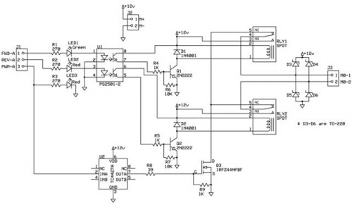
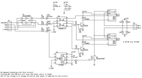
I have posted a motor controller design that is supposed to be simple, robust, cost effective, and able to handle high currents. Above is a schematic of the first part of the design. I will post an updated version to include a PIC to accept commands from a PC, Microcontroller, etc. and provide the direction/PWM signals to the H-bridge. I am still working on the PCB but here is what I have done so far for review/critism. What is not shown in the schematic are the in-line fuses for protection.

For the PIC, I use MBasic and PicBasic Pro to write the code. This should convert easly to the BS2 and PicAxe.

More to come and thanks for whatever welcome I may receive (hopefully a warm one).


** Updated 04 January 2009 **

Here is an updated version based on advice provided below. Again, if you find any errors let me know.

Thanks to all who provide help/advice and to those who show interest. I know there are easier ways to do this but this is sorta an addiction now.

Updated controller


** Updated 10 Jan 2009 **

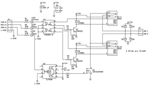
I updated the schematic again. As suggested I changed the MOSFET driver to a TLP250 and dropped the 1K resistor across the Gate to source.

Update the schematic to show that the logic grounds are isolated from the dirty motor grounds.


** Updated 10 Jan 2009 **

Updated the schematic for those that want to save an I/O pin. There is a Hex Inverter/Buffer circuit (U1) that feeds the inputs of the Optoisolator (U2). If you look at the wiring for the Hex Inverter you will notice that the output of the second inverter feeds the input of the first inverter. So, when a logic 1 is placed across pin-3 it is inverted into a logic 0 which turns off the Reverse Relay. A logic 0 is also placed at the input of the first inverter which gets converted to a logic 1 on its output and turns on the Forward Relay.

By using the inverter circuit you will no longer have the capability for dynamic breaking. In other words, one of the relays will be active as longs as powered is applied to the circuit. Disabling the PWM signal will keep the motor from turning.


** Updated 11 Jan 2009 **

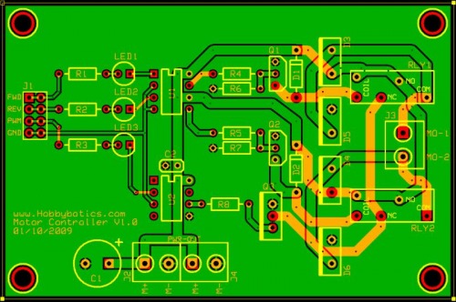
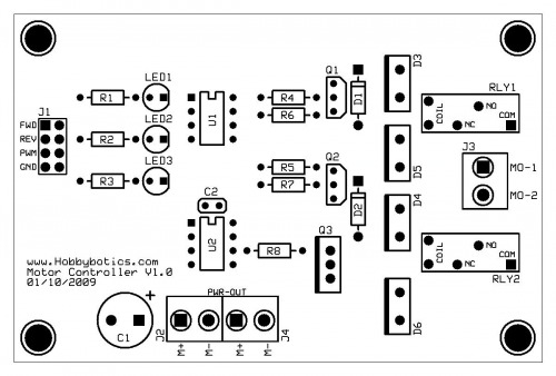
Finished the PCB design. Once boards are complete will test and post schematic and board files once any kinks are worked out.
** Updated 22 January 2009 **

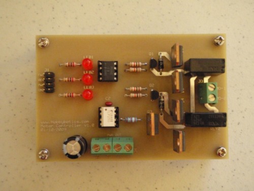
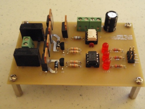
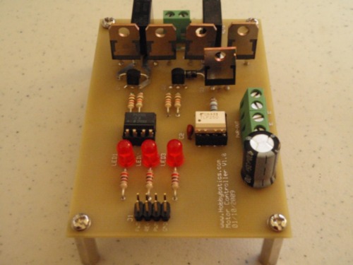
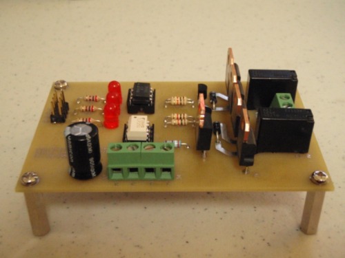
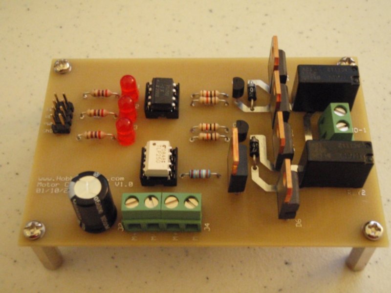
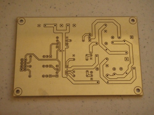
I got the prototype boards back from the manufacture two days after I sent them off. As you'll see below, the quality is excellent. Tonight I populated the board and checked out functionality with a multimeter prior to testing with a motor. I managed to get everything put together right so on to the smoke check. I hooked up a good size motor with a lot of torque and applied power. The motor moved in both directions and the MOSFET did not even get warm. This test was applying full power to the motor and not PWM. Next, I'll write some code and test functionality with PWM hooked to my Oscope so I can check the signals and see how high I can take the frequency. I'll get around to posting some video but, in the mean time, here are some pictures of one of the finished boards.
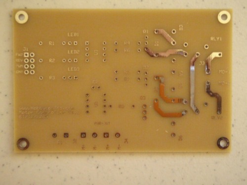
PCB Top

PCB Bottom

** Bill Of Materials **

Component Description Part Number Vendor Cost
C1 220 uF P10325-ND Digikey $0.72
C2 0.1uF BC1114CT-ND Digikey $0.20
D1 1N4001 Rectifier 50V 1A 1N4001DICT-ND Digikey $0.30
D2 1N4001 Rectifier 50V 1A 1N4001DICT-ND Digikey $0.30
D3 Schottky Diode 45V 15A STPS1545D Mouser $0.80
D4 Schottky Diode 45V 15A STPS1545D Mouser $0.80
D5 Schottky Diode 45V 15A STPS1545D Mouser $0.80
D6 Schottky Diode 45V 15A STPS1545D Mouser $0.80
J1 4-Pin Header, Male 2077095 Jameco $0.19
J2 Screw Terminal, 2-Pin 160785 Jameco $0.65
J3 Screw Terminal, 2-Pin 160785 Jameco $0.65
J4 Screw Terminal, 2-Pin 160785 Jameco $0.65
LED1 3mm Red, T1 253278 Jameco $0.26
LED2 3mm Red, T1 253278 Jameco $0.26
LED3 3mm Red, T1 253278 Jameco $0.26
Q1 2N2222 NPN Bipolar Transistor 600mA 75V P2N2222AG Mouser $0.21
Q2 2N2222 NPN Bipolar Transistor 600mA 75V P2N2222AG Mouser $0.21
Q3 IRFZ44N Single-Gate MOSFET Transistor N-Channel 60V 50A IRFZ44NPBF Mouser $1.30
R1 270 Carbon Film 1/4W P270BACT-ND Digikey $0.08
R2 270 Carbon Film 1/4W P270BACT-ND Digikey $0.08
R3 270 Carbon Film 1/4W P270BACT-ND Digikey $0.08
R4 1K Carbon Film 1/4W P1.0KBACT-ND Digikey $0.08
R5 1K Carbon Film 1/4W P1.0KBACT-ND Digikey $0.08
R6 10K Carbon Film 1/4W P10KBACT-ND Digikey $0.08
R7 10K Carbon Film 1/4W P10KBACT-ND Digikey $0.08
R8 39 Metal Film 1/4W 39.2XBK-ND Digikey $0.11
RLY1 SPDT 12V @ 20A ACT112 Mouser $2.17
RLY2 SPDT 12V @ 20A ACT112 Mouser $2.17
U1 PS2501-2 Dual NPN Phototransistor PS2501-2-A Mouser $0.87
U2 TLP250 Photocoupler IGBT MOSFET Driver TLP250F-ND Digikey $1.88
PCB Printed Circuit Board N/A
ExpressPCB $20.28
Total
$37.40

** 24 January 2009 **

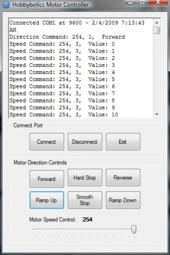
I added a few of pictures of the test application and the temporary PWM controller used for testing.
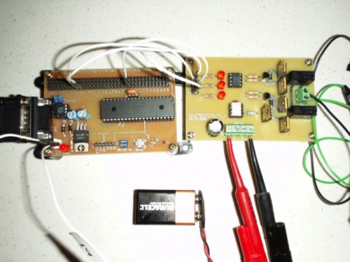
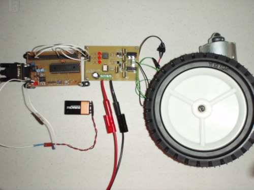
Temporary PWM Controller and Motor Controller

** 02 February 2009 **

Added a crappy video of the motor controller being tested.

High-Current Motor Driver


This is a companion discussion topic for the original entry at https://community.robotshop.com/robots/show/big-motor-driver-inspired-by-chris-the-carpenter

Well it’s certainly big

Well it’s certainly big


Edit: That’s better.

Sorry, took a little use to

Sorry, took a little use to getting the hang of how the posts will look.


"Common sense is not so common" Thomas Paine

Hey! this post has my name in it!!!

Nice to meet you, my friend.

Well, you have obviously seen the motor controller I made (the one controlling Walter) and I can say that with the exception of a very few bugs it is pretty bullet-proof. The only change I have made that is not in the post is that I added 2 resistors between the MOSFET driver IC and the MOSFETs. I am really surprised this made such a difference, but I have yet to smoke a FET since and at it’s peak, I am working with about 50-60 amps total.

I am stoked to see what you came up with, the whole “big motor controller” conversation was a good one around here!

Welcome--

Nice protective change but …
I like the addition of the opto-isolators, to protect the controlling circuits. But there appears to only be half the flyback diodes (sort of but not quite from motor lead to power, none from ground to motor lead) and no fast shut off for the PWM FET. Might only go up to 2 kHz PWM reliably.

Thanks for the welcome,I

Thanks for the welcome,

I placed the high-speed Schotkky clamping diodes in the circuit to protect the MOSFET from the CEMF generated by the motor as the power is switched on/off via the PWM signal. This will help keep the FET from generating to much heat and destroying itself. Also, the Optoisolator is a fast-switching type that will help ensure the MOSFET is switched on/off quickly instead of ramping. The opto has a fast rise/fall time. The relays are set up in an H-bridge configuration while the FET is used for the PWM signal. I am gonna build this over the next couple of days before I make the PCB. If anyone finds errors in this design please post them.


Thanks to all,

Curtis

"Common sense is not so common" Thomas Paine

Correct me if I am wrong but

Correct me if I am wrong but there are flyback diodes (D1 and D2) across the relay coils and D3 and D4 for the motor windings. Fast shutoff for the FET should happen through the speed of the opto. It was chosen for fast rise/fall. Do I need to add more diodes into the circuit?


"Common sense is not so common" Thomas Paine

Ok, some corrections

The D1 and D2 diodes may or may not be needed for the relay coils, depending upon the amount of current required by those coils. As is, they are installed correctly to allow for any flyback that may occur there.

The D3 and D4 schottky diodes are placed to allow the motor reverse current to flow only if the relays are in a Forward or Reverse active mode. If the relays lose power while the motor is running, there will be no path for the flyback voltage to travel, and something could pop. That is why best practice on flyback diodes for an h-bridge configuration has 4 diodes, 2 going from ground to each motor lead , and 2 going from each motor lead to to power.

The opto does nothing to shut-off the FET quickly, the FET must bleed off charge through the 10k resistor placed there for cutoff. Using the gate capacitance of the FET to get an RC time constant, I think you’ll be able to calculate that switch off time won’t be very fast. Additionally the opto only delivers a few mA, maybe a max of 50 mA in switching on, so there will be an extended turn on time as the opto tries to charge the FET gate capacitance up to turn it on. There are high speed opto FET drivers, but the PS2501 appears to be a more high speed communucations device, for driving other BJTs rather than FETs. The Toshiba TLP250 is an opto capable of FET driving.

Thanks for the

Thanks for the corrections/suggestions. I understand exactly what you are saying. I did not consider the condition of losing power to the relays with the motor running. I’ll also look into the TLP250.

Thanks for the help,

Curtis

“Common sense is not so common” Thomas Paine

I dont…
have a clue what any of the diagram means, but im looking forward to this as im after a decent motor control unit for my projects. I look forward to seeing what the end product is. Good effort mate.

Hey Curtis, great to have

Hey Curtis, great to have you here :slight_smile:

Lookin forward to see who you are going to drive around (chris is using he’s bots to transport he’s wife)

PS: please drop the funny joke in your auto-signature, it makes pages crap to read (see Best Practice, front page)

PPS: Nice avatar, good energy :smiley:

Thanks for the kind wordsI

Thanks for the kind words

I have a number of projects that I’m thinking of using the controller for. One being a snowball launching terret gun. As I’m in the Air Force and have been stationed at Northern Tier (North Dakota for 13 years) or currently Cheyenne (1st year) and the weather can be a bit extreme. I want to do something fun (hehe) for the kids. During the summer I want to convert it into a water cannon. It’ll all be computer controlled and I’m using ZigBee controllers for communication.

I have dropped the auto-signature as I don’t want to offend anyone. It was mainly meant to be a personal reminder that things we say should be common sense tend not to be so common until after the fact.

Cool! No offense intended,

Cool! No offense intended, sorry if I was sounding rude, people often tell me I sound rude in English - it is just a translation / cultural thingey :slight_smile:

Oh yeah…

Oh yeah,

If you heard Frits speak Danish (or whatever) it sound like he is singing… It’s just the English where he sounds like a jerk…

The schematic does not show
The schematic does not show it but I added a bypass capacitor between VDD and GND as the TC4427A Mosfet driver datasheet recommends it.

Lost isolation
The change was good but isolation was lost. The TLP250 suggested can be found at Digikey for $1.88 and would get you back the isolation, which is a very good feature of this design. Oh, the 10k resistor between the gate and source of the FET is not needed with an active driver like the TC4427 or TLP250. The small 39 ohm gate resistor is still a help though. Good thinking on adding the capacitor.

You should see me dance!

Thanks,I did order some

Thanks,

I did order some TLP250 chips. I’ll update the schematic and give those a try. I was worried about losing the isolation with using the TC4427.

You changed your hair color

You changed your hair color Frits http://www.youtube.com/watch?v=sRnWRMA8VRA

Hi Curtis,It’s great to see

Hi Curtis,

It’s great to see you fight the good fight of motor controller design.

I have a couple of suggestions you might consider.

1. electrical isolation is a very good thing, especially for larger current motors - I have uhh I mean, I know people who have smoked a large amount of work in a micro-second because it was more expedient to make the controller without isolation. It looks like you’ve done this in your last revision.

2. if you aren’t going to do high-side braking or low-side braking - then why not save a BIT (they are precious you know?) and combine FWD & REV into a single bit - where high is FWD and low is REV. This could be done with a small NPN & PNP with combined base and output to your current FWD-A & REV-A

Regards,
GroG