


Big Motor Driver (Inspired by Chris the Carpenter)
I'm not sure how I stumbled upon this site but find myself visiting it on a daily basis now. I spent the better part of a week reading through a numerous amount of posts and became inspired by some of the designs.
One design that caught my interest was the motor controller made by Chris the Carpenter (with contributions from others). So, instead of mooching information off of the site I decided I should contribute something.
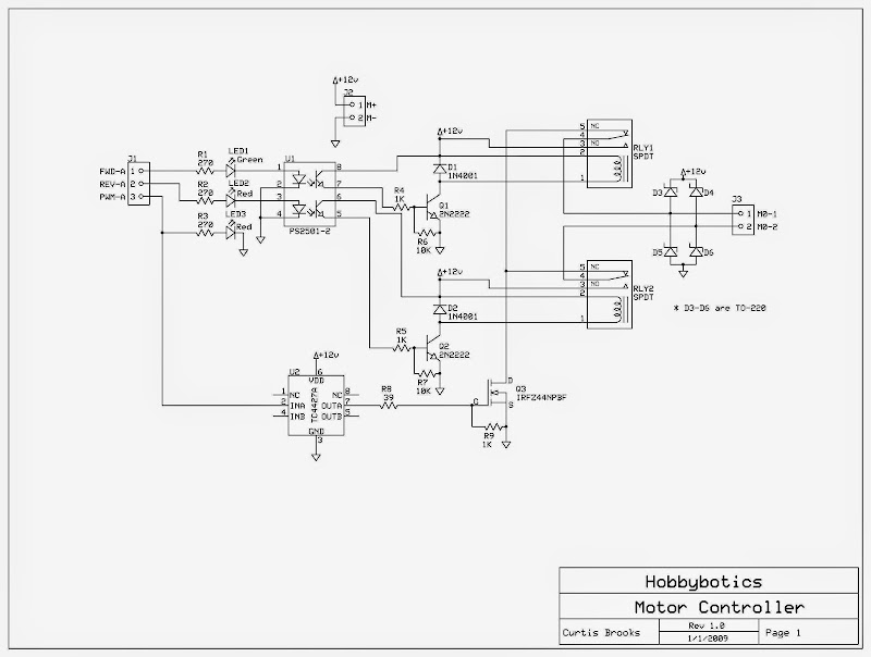
I have posted a motor controller design that is supposed to be simple, robust, cost effective, and able to handle high currents. Above is a schematic of the first part of the design. I will post an updated version to include a PIC to accept commands from a PC, Microcontroller, etc. and provide the direction/PWM signals to the H-bridge. I am still working on the PCB but here is what I have done so far for review/critism. What is not shown in the schematic are the in-line fuses for protection.
For the PIC, I use MBasic and PicBasic Pro to write the code. This should convert easly to the BS2 and PicAxe.
More to come and thanks for whatever welcome I may receive (hopefully a warm one).
** Updated 04 January 2009 **
Here is an updated version based on advice provided below. Again, if you find any errors let me know.
Thanks to all who provide help/advice and to those who show interest. I know there are easier ways to do this but this is sorta an addiction now.
** Updated 10 Jan 2009 **
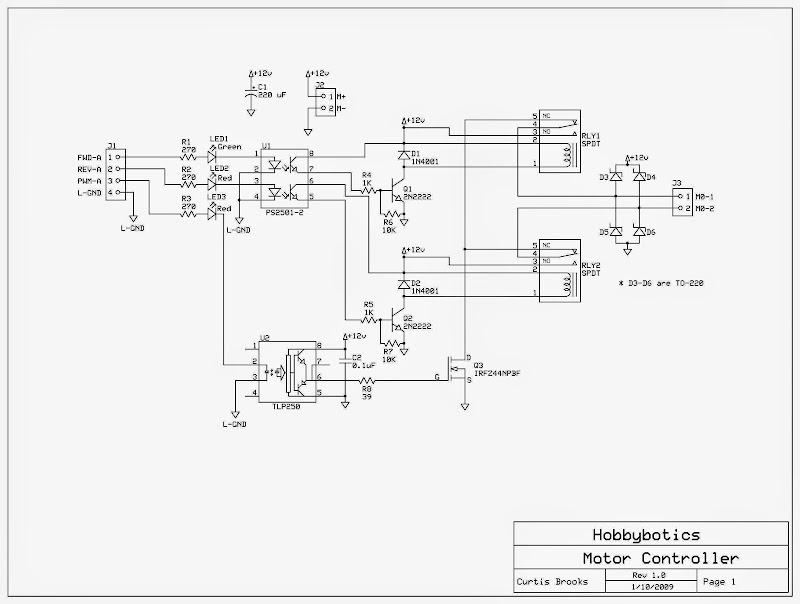
I updated the schematic again. As suggested I changed the MOSFET driver to a TLP250 and dropped the 1K resistor across the Gate to source.
Update the schematic to show that the logic grounds are isolated from the dirty motor grounds.
** Updated 10 Jan 2009 **
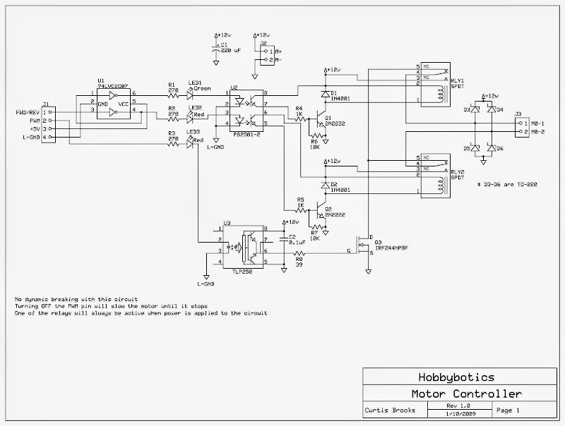
Updated the schematic for those that want to save an I/O pin. There is a Hex Inverter/Buffer circuit (U1) that feeds the inputs of the Optoisolator (U2). If you look at the wiring for the Hex Inverter you will notice that the output of the second inverter feeds the input of the first inverter. So, when a logic 1 is placed across pin-3 it is inverted into a logic 0 which turns off the Reverse Relay. A logic 0 is also placed at the input of the first inverter which gets converted to a logic 1 on its output and turns on the Forward Relay.
By using the inverter circuit you will no longer have the capability for dynamic breaking. In other words, one of the relays will be active as longs as powered is applied to the circuit. Disabling the PWM signal will keep the motor from turning.
** Updated 11 Jan 2009 **
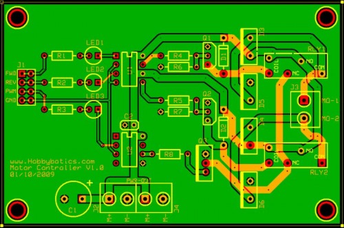
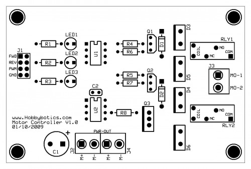
Finished the PCB design. Once boards are complete will test and post schematic and board files once any kinks are worked out.
** Updated 22 January 2009 **
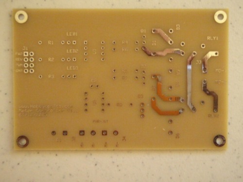
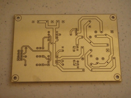
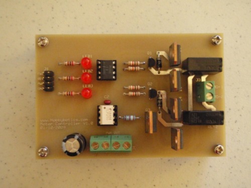
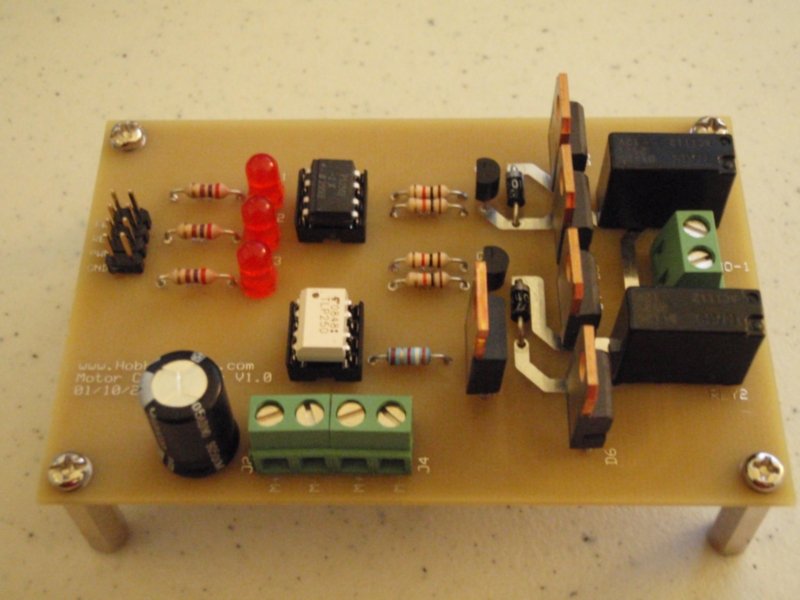
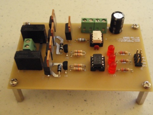
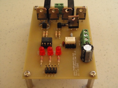
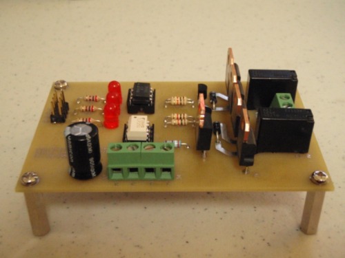
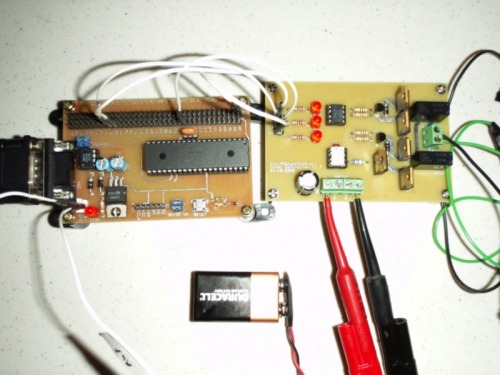
I got the prototype boards back from the manufacture two days after I sent them off. As you'll see below, the quality is excellent. Tonight I populated the board and checked out functionality with a multimeter prior to testing with a motor. I managed to get everything put together right so on to the smoke check. I hooked up a good size motor with a lot of torque and applied power. The motor moved in both directions and the MOSFET did not even get warm. This test was applying full power to the motor and not PWM. Next, I'll write some code and test functionality with PWM hooked to my Oscope so I can check the signals and see how high I can take the frequency. I'll get around to posting some video but, in the mean time, here are some pictures of one of the finished boards.
** Bill Of Materials **
| Component | Description | Part Number | Vendor | Cost |
| C1 | 220 uF | P10325-ND | Digikey | $0.72 |
| C2 | 0.1uF | BC1114CT-ND | Digikey | $0.20 |
| D1 | 1N4001 Rectifier 50V 1A | 1N4001DICT-ND | Digikey | $0.30 |
| D2 | 1N4001 Rectifier 50V 1A | 1N4001DICT-ND | Digikey | $0.30 |
| D3 | Schottky Diode 45V 15A | STPS1545D | Mouser | $0.80 |
| D4 | Schottky Diode 45V 15A | STPS1545D | Mouser | $0.80 |
| D5 | Schottky Diode 45V 15A | STPS1545D | Mouser | $0.80 |
| D6 | Schottky Diode 45V 15A | STPS1545D | Mouser | $0.80 |
| J1 | 4-Pin Header, Male | 2077095 | Jameco | $0.19 |
| J2 | Screw Terminal, 2-Pin | 160785 | Jameco | $0.65 |
| J3 | Screw Terminal, 2-Pin | 160785 | Jameco | $0.65 |
| J4 | Screw Terminal, 2-Pin | 160785 | Jameco | $0.65 |
| LED1 | 3mm Red, T1 | 253278 | Jameco | $0.26 |
| LED2 | 3mm Red, T1 | 253278 | Jameco | $0.26 |
| LED3 | 3mm Red, T1 | 253278 | Jameco | $0.26 |
| Q1 | 2N2222 NPN Bipolar Transistor 600mA 75V | P2N2222AG | Mouser | $0.21 |
| Q2 | 2N2222 NPN Bipolar Transistor 600mA 75V | P2N2222AG | Mouser | $0.21 |
| Q3 | IRFZ44N Single-Gate MOSFET Transistor N-Channel 60V 50A | IRFZ44NPBF | Mouser | $1.30 |
| R1 | 270 Carbon Film 1/4W | P270BACT-ND | Digikey | $0.08 |
| R2 | 270 Carbon Film 1/4W | P270BACT-ND | Digikey | $0.08 |
| R3 | 270 Carbon Film 1/4W | P270BACT-ND | Digikey | $0.08 |
| R4 | 1K Carbon Film 1/4W | P1.0KBACT-ND | Digikey | $0.08 |
| R5 | 1K Carbon Film 1/4W | P1.0KBACT-ND | Digikey | $0.08 |
| R6 | 10K Carbon Film 1/4W | P10KBACT-ND | Digikey | $0.08 |
| R7 | 10K Carbon Film 1/4W | P10KBACT-ND | Digikey | $0.08 |
| R8 | 39 Metal Film 1/4W | 39.2XBK-ND | Digikey | $0.11 |
| RLY1 | SPDT 12V @ 20A | ACT112 | Mouser | $2.17 |
| RLY2 | SPDT 12V @ 20A | ACT112 | Mouser | $2.17 |
| U1 | PS2501-2 Dual NPN Phototransistor | PS2501-2-A | Mouser | $0.87 |
| U2 | TLP250 Photocoupler IGBT MOSFET Driver | TLP250F-ND | Digikey | $1.88 |
| PCB | Printed Circuit Board | N/A | ExpressPCB | $20.28 |
| Total | ||||
| $37.40 |
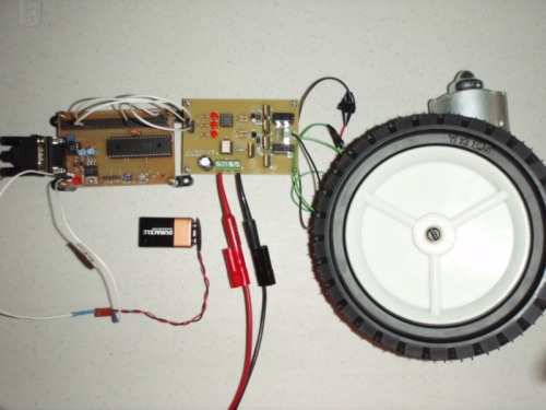
** 24 January 2009 **
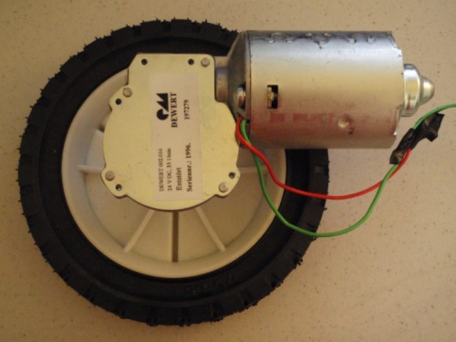
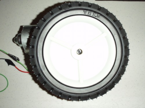
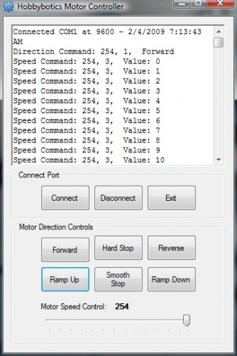
I added a few of pictures of the test application and the temporary PWM controller used for testing.
** 02 February 2009 **
Added a crappy video of the motor controller being tested.
High-Current Motor Driver