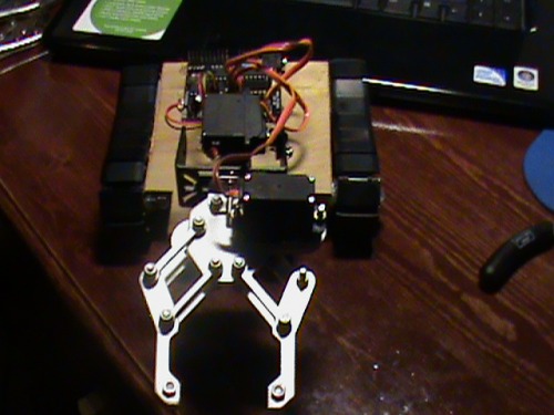
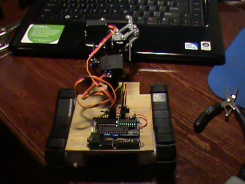
B.I.L. (Because I'm Lazy)

To start, I'd like to say this is my first robot, but, since I had electronic- experience, and so many people have done the SHR, and I had a good idea, B.I.L. was born! Also, I'm sorry for not posting my progress, got caught up in the moment i geuss :)

The plan was (is) to make a robot that can go somewhere (down the hall, across the room, across my desk, etc.) and retrieve something for me, and be controlled via  my T.V. remote (actully, now I'm thinking it'd be better to have it be radio- controlled; I wont have to worry about line-of-sight and slow data transmission :D)

Not much to say, except that I had a little trouble getting the treads tight, and cannot work on the IR control, as I don't have a pull- up resistor (yet) :(

Here's some more pictures:
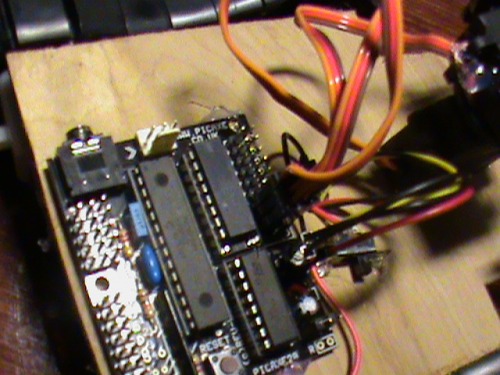
Sorry for the quality of the pictures... more updates and videos to come soon.

UPDATE:

Instead of IR communication, which i couldn't get to work, I've decided to use these RF modules:

Reciever

Transmitter

I think this will be faster and I won't have to worry about line-of-sight.

I'm pretty sure this would be how to connect the reciever to my 28x board:
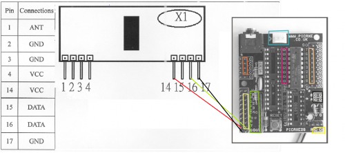
I'm not going to post a picture for my 20x2 picaxe chip-setup, becuase it is so simple.. data to input 6, Vcc to +3v, Ground to Ground.

P.S. I think that I wouldn't need an antenna for either modules, but please correct me if I'm wrong.


  • Actuators / output devices: 2 geared motors, 3 servos
  • Control method: (Will be) Infra Red controlled via my T.V. Remote, possibly radio0 controlled
  • CPU: Picaxe 28x1
  • Power source: 3 x AAA
  • Programming language: Picaxe basic
  • Target environment: indoors

This is a companion discussion topic for the original entry at https://community.robotshop.com/robots/show/b-i-l-because-im-lazy

Great first robot ! Keep it

Great first robot ! Keep it going =)

Radio Shack should carry pull-up resistors. What you want is a resistor that is about 10K but really any large value will do (sometimes I use 1K). The resistor just needs to be a high value so that the voltage drop across it will be significant enough to keep your I/O pin in an ON state.

Thanks

Thats a relief… I really didn’t want to have to order one :slight_smile:


Well, Radioshack didn’t have them… had no idea what pull- up resistors were :frowning:

If the Radioshack you went

If the Radioshack you went to has resistors then they probably have some high value ones you can use as a pull up resistor. The term “pull-up resistor” does not mean it is a special kind of component. It is just a resistor. Next time ask for a 10K resistor. No need to mention to them that it is a pull up resistor. 

I was thinking that

I was half- thinking that it might be just a term used with the use of the resistor, but I wasn’t sure… is there any special way I have to wire it up?

Here is a example

pullup.png

Thanks

That helped alot…

One more thing

Well, i got the resistor today, but for got the capacitator… oh well… so starting on the IR receiver tomorrow.

IR Reciever

Well, I searched IR circuits on LMR and found this, but I’m not sure as to how to wire it to the board… here’s my current circuit and geuss as to where the wires should go… (P.S. I am using this reciever).

I can’t comment on the

I can’t comment on the circuit diagram you pulled from the other thread.  But in your connection diagram you are connecting “signal” (pin 1 of the IR sensor) back to Vcc via the green line.  Digital I/O “0” is right below that - the top-most pin within the block outlined in yellow.  That’s where you will want to connect the sensor output.

So…

So, other than that, it looks alright?


Well…

This is now my current circuit and how i have it wired to the 28x1, but, I cant seem to get IRIN to work… what’s a good test-code for it?

Infra_Red_Reciever_1.png

Replied to your other IR forum post question

It’s been a moment or two since I worked with IR so I can’t tell you exactly what to use. I’m at the sweatshop right now but I will dig up the code I used for Crumbot’s IR programming when I get home.

edit-

I found the snippet in the code but it’s ugly at best. The only thing you could learn from it is to us it as an example of how not to navigate through your subroutines. My take home message here is: For every GOSUB you need a RETURN. It something to consider if you like to use the GOTO command, i.e. don’t do it before RETURNing out of a sub you GOSUB or CALLed to. My code will eventually have a stack overflow error from bad structure like that.

Oops

ignore this…

Almost

Your ground connection needs to move down a hole. I believe that is still a V+ connection you’ve got it tied to currently. It might not be but I’m 99.99999% sure the one below it is a GND for certain.

This code passes syntax at least

This is similar to the structure I intended for in my IR code communication. For this I assume you have an LED/330ohm resistor you could use as a blinky indicator. You’ll need to assign a pin number to my pseudo-variable “LED_pin” for the LED. Tie the cathode end of the led to ground and the positive side to the pin.

When you press “1” on the remote it should light the LED for one second and then turn it off again.


symbol infra=b13

main:
infra=0
gosub ir_read
goto ir_control

ir_read:
irin [50,ir_timeout],0,infra
return

ir_timeout:
return

ir_control:
if infra = 1 then gosub LED
goto main

LED:
high LED_pin
pause 1000
low LED_pin
pause 250
return