Autonomous Underwater Vehicle

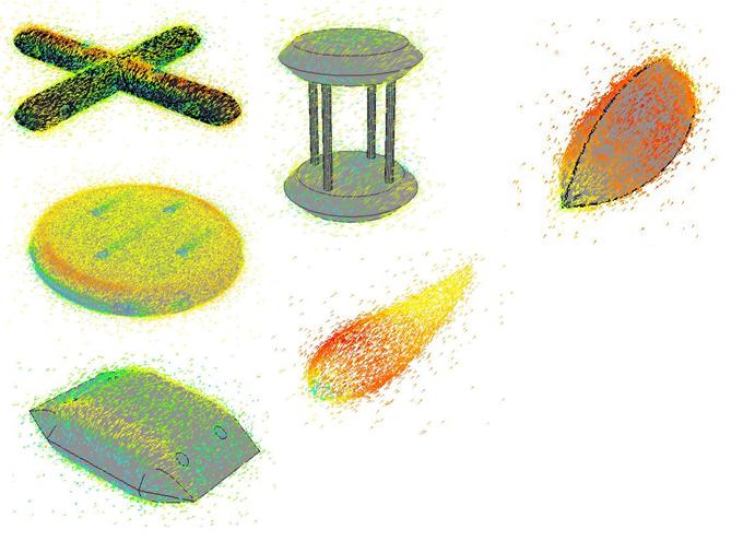
The aim of the project was to design and build an underwater vehicle with an emphasis on stability such that it may possible to perform light well intervention. This evolved into a project with a (relatively) streamlined shape and a control system capable of maintaining a stable position, such that, upon rotating due to external force, the craft is capable of actuating back to it's original orientation. Some of the initial concepts can be seen here. CFD anaylsis was carried out to determine the drag coefficients of the various concepts.

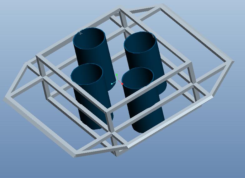
The concept on the bottom left was chosen for further development. The craft's frame is made from 12mm mild steel bar, model shown below.

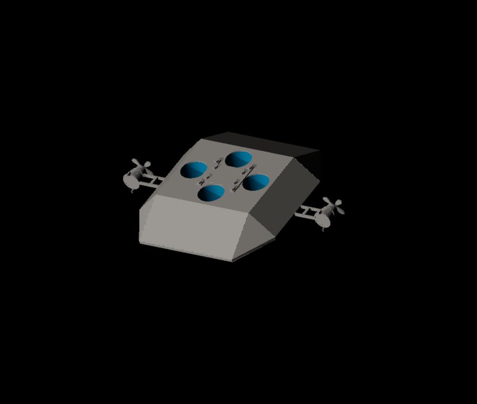
The skin of the craft is 2mm mild steel sheeting. The final concept can be seen below.

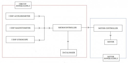
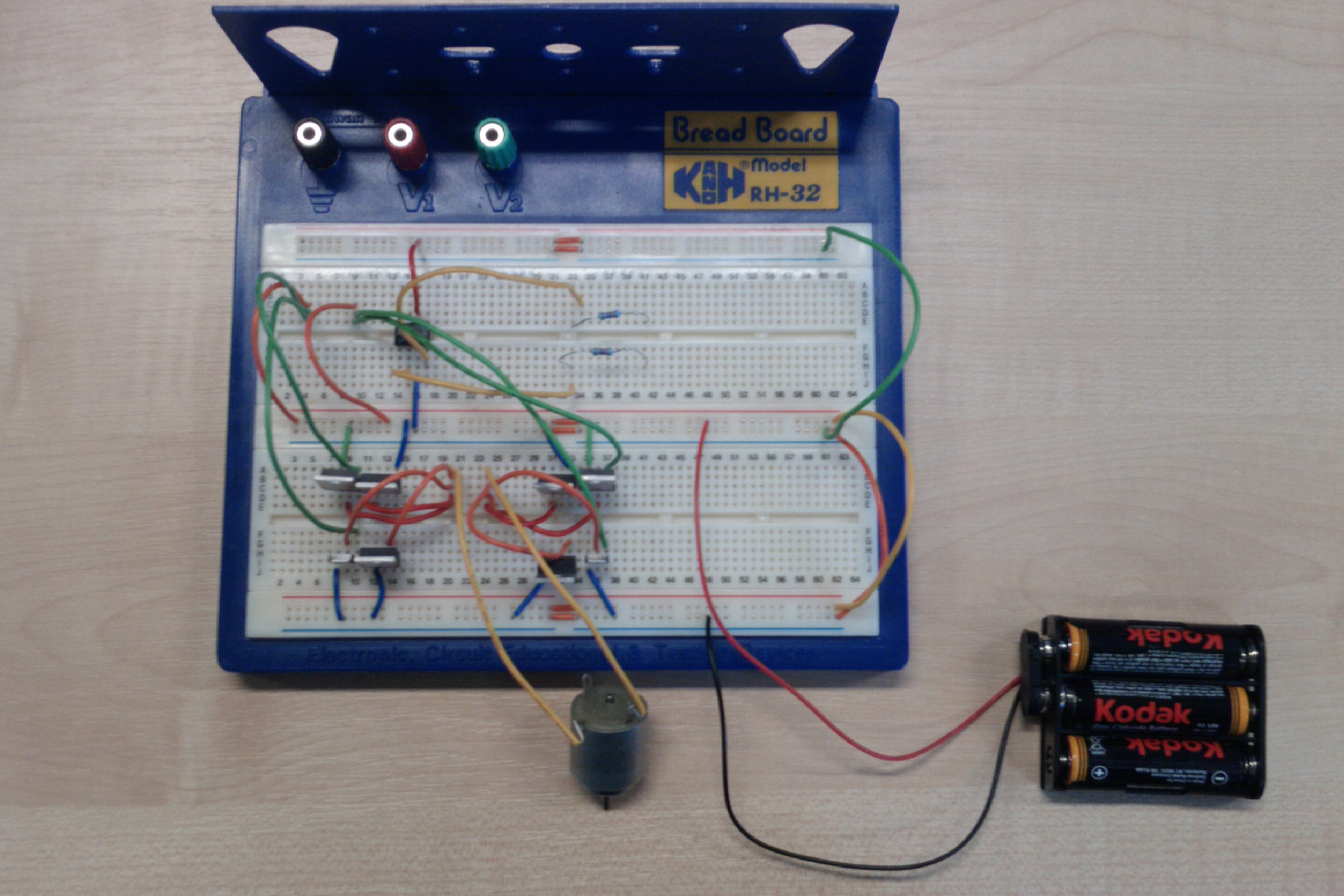
The sensor array of the project is sparkfun's 9DOF razor IMU, which has a 3DOF accelerometer, 3DOF gyroscope and a 3DOF magnetometer. This feeds into an arduino mega 2560, which has control of six 12v DC motors which were cannibalised from a Rule 750GPH Bilge Pump. They are water proof, and have 50mm model boat propellers attached to them. They draw about 5.5~6.5A. They are controlled via. six motor controllers. These are custom made high current H bridges. They're currently a work in progress. The craft also has a data logger capable of logging any changes in orientation in pitch, yaw and roll. The basic idea of the electronics can be seen below.

The project is entering the final construction stage and hopefully will be finished in the next fortnight. 

H-Bridge


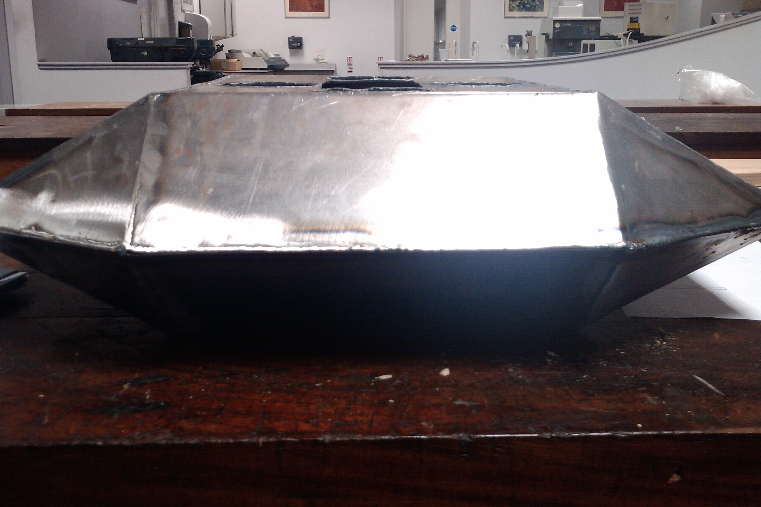
Current State, Profile

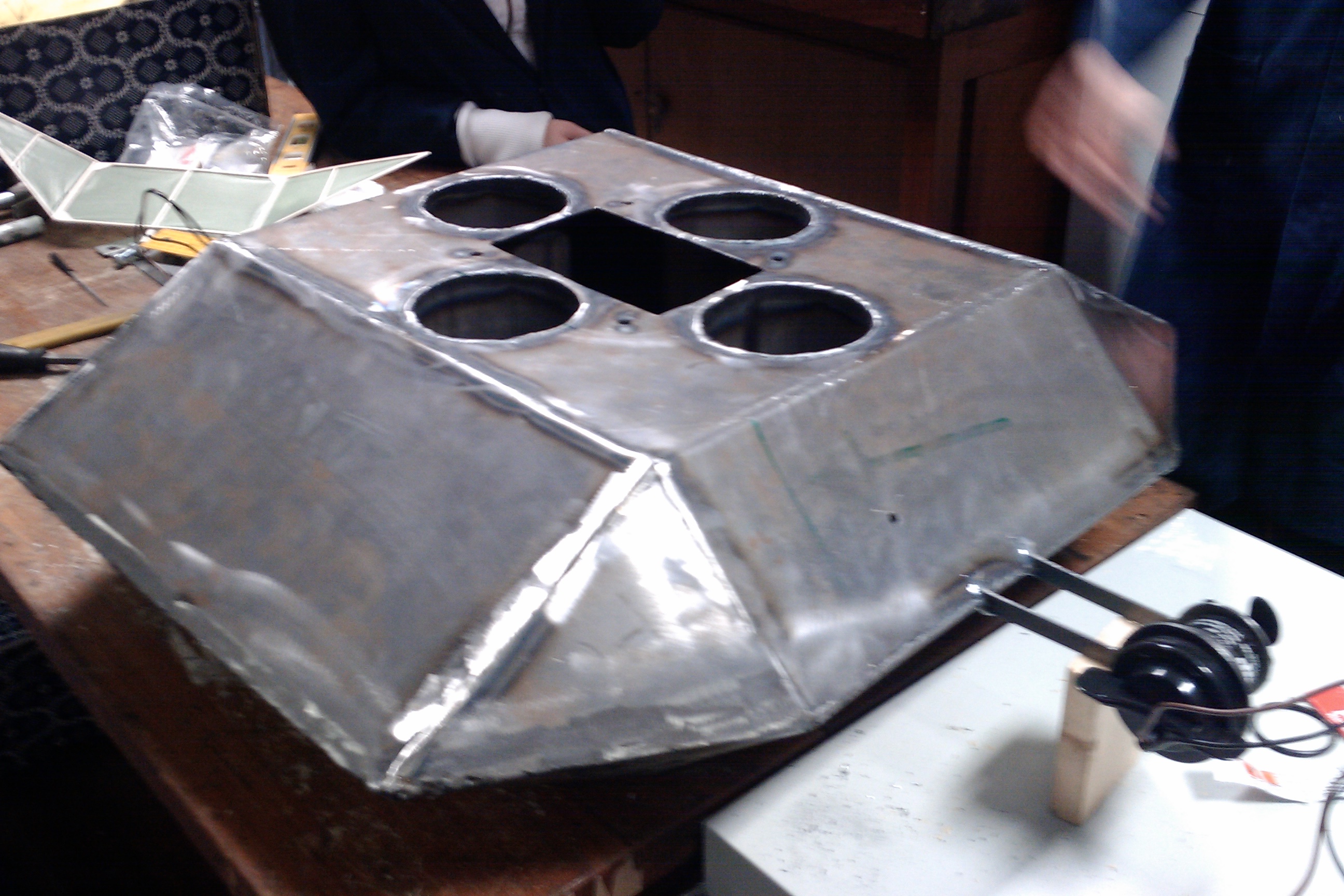
Current State, showing external mounts. 

Update 04/04/11:

 A flotation test was carried out in a water tank. As you can see the craft floated with roughly 55% submerged. 0.5, 1 and 2 kg bags of sand were made up and used to appropriately weight the craft, to make the AUV as close to neutrally buoyant as possible. 

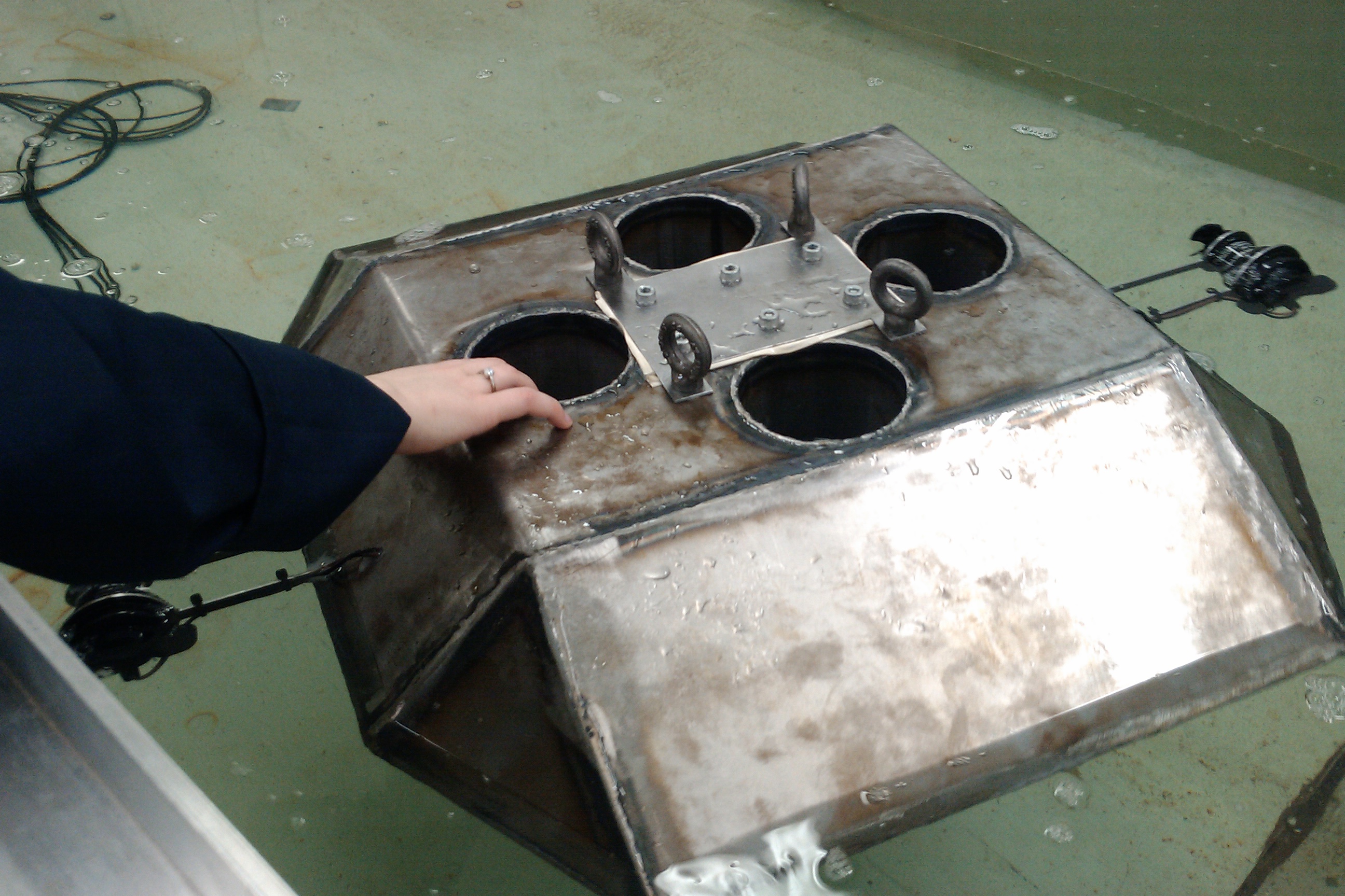
Notice the M8 lifting eyes used to aid lifting the AUV in and out of the water. Upon submerging it was discovered water was entering the inside of the craft. The threads of all the bolts were vaselined, and rubber washers were used to guarantee a seal. The holes where the motor wires entered the craft were epoxied again, and siliconed. Subsequent testing confirmed the craft was water tight. 


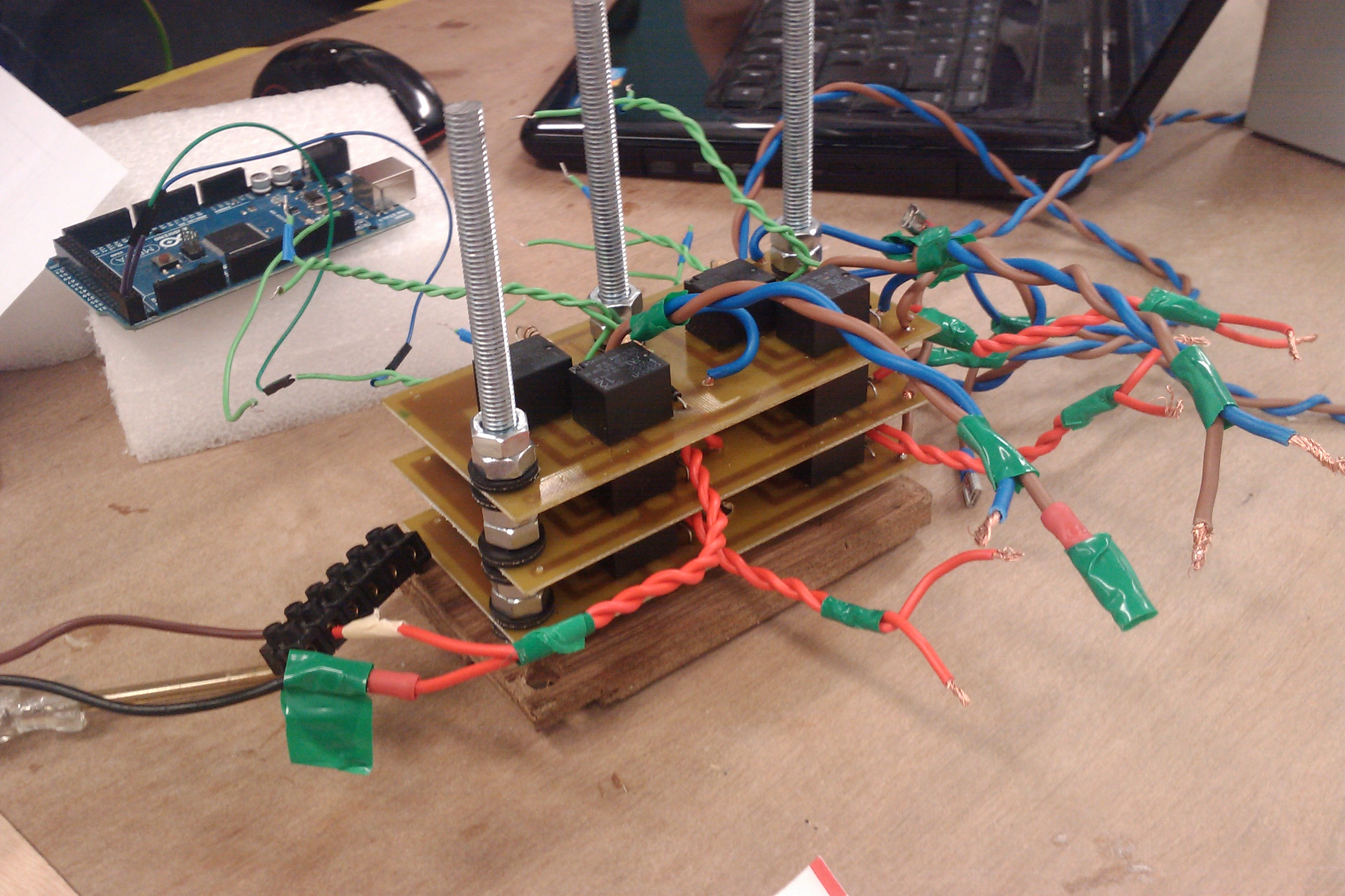
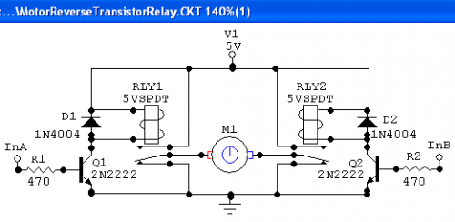
Shown above is the motor driver boards and weeks of painstaking effort. At first it was hoped to use power mosfets to construct an h-bridge. However after several melted mosfets, on-fire transistors and shorted PCBs, the decisions was taken to opt for mechanical relays instead. Two SPDT relays were arranged in an H bridge configuration, shown below:

H-Bridge Schematic

Six motor controllers were built, on three PCB boards. The only deviation was using relays rated at 12v/10A instead of 5v. Each board is powered by one 12v Lead acid battery. Tracks on the PCB are sitting at just over 3mm. 

PCB schematic

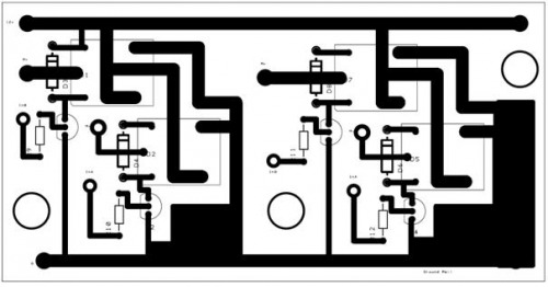
Note mistakes on this board. Three of the relays do not recieve power from the power rail, this was correcting by soldering wires on. Also some of the tracks (where the motors will be drawing their current) are far too thin and were made thicker before manufacture. Close up of boards shown below:

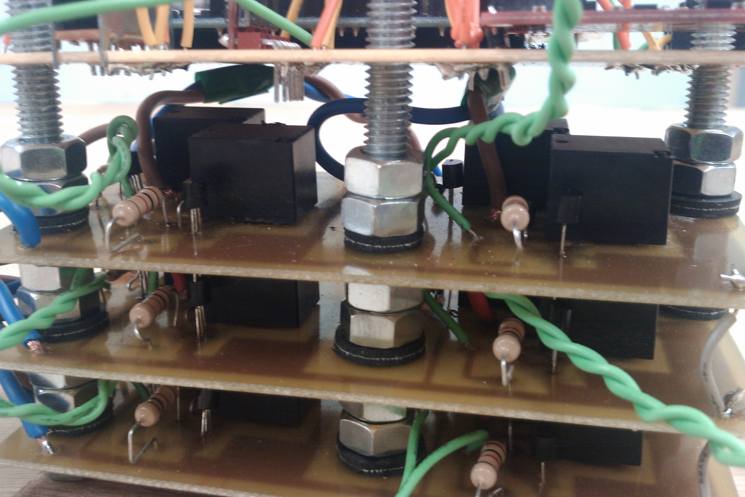
The final electronics tower can be seen below:

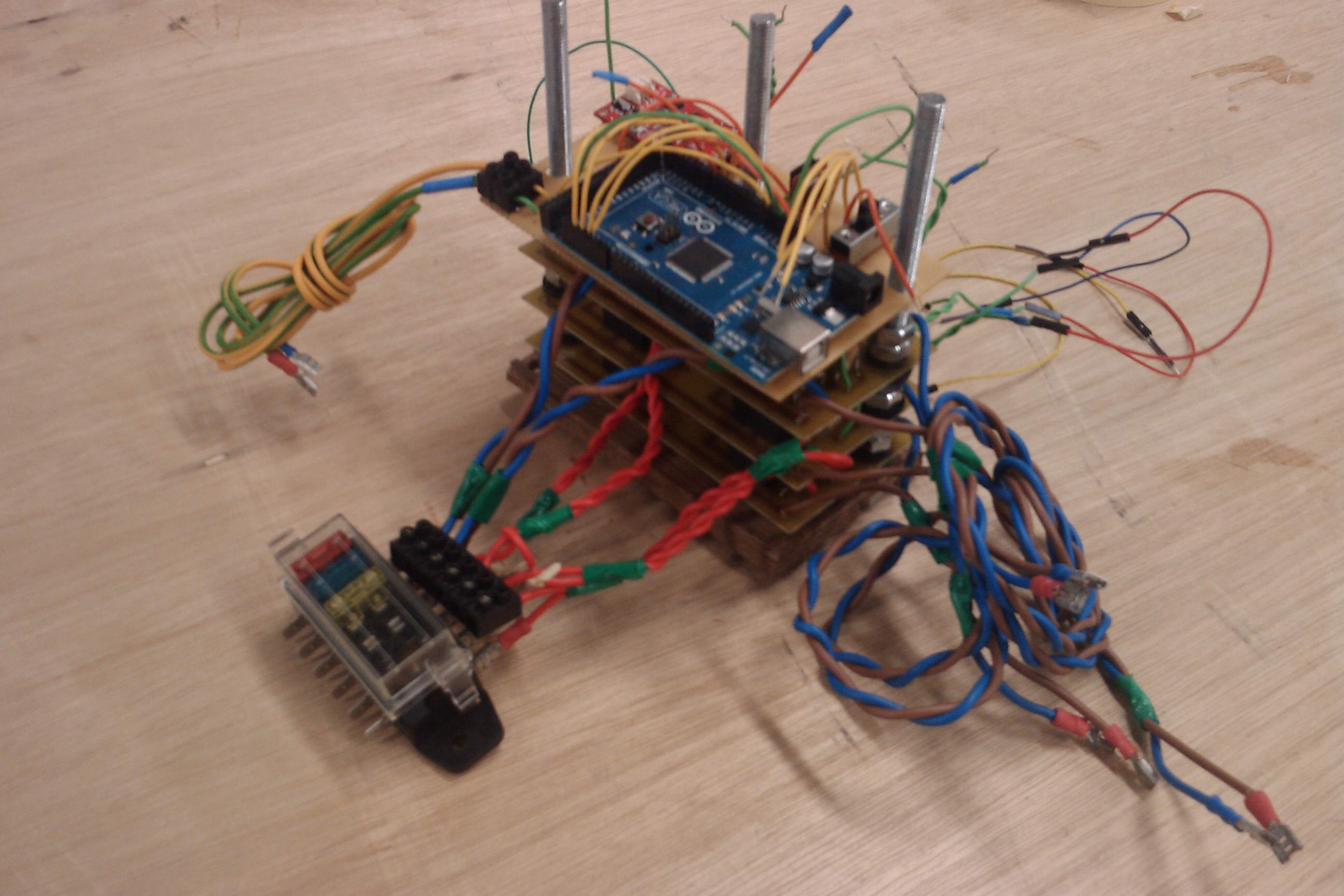
Show is the small fuse box, obtained from ebay. It used blade fuses. The size of fuse is yet to be determined. The power wires (blue/brown) can be seen, as can be motor wires (red). At the rear of the picture is the arduino control wires. On top is a piece of copper strip board. The IMU / Datalogger and Arduino was secured onto this strip board. The Arduino was held in place using velcro. 

Final testing will be put up soon.


Update 08/04/2011 - Final Testing Complete. More Videos to follow...


Path Movement Underwater, Autonomously maintains a stable position in the water.

  • Actuators / output devices: 6 x 12v DC Motors
  • Control method: autonomous
  • CPU: Arduino Mega 2560
  • Power source: 4 x 12v Lead Acid
  • Programming language: C#
  • Sensors / input devices: 3DOF Accelerometer, 3DOF Gyroscope, 3DOF Magnetometer.
  • Target environment: underwater

This is a companion discussion topic for the original entry at https://community.robotshop.com/robots/show/autonomous-underwater-vehicle

Score…

First use of the term “fortnight” on LMR!!


Did you pressure test the

Did you pressure test the vessel yet?

Very interesting. Don’t see


Very interesting. Don’t see many underwater robots on LMR. One step closer to a design to use in space or in the space station.


No, not yet. We’re finishing

No, not yet. We’re finishing off the hatch cover and should be submerging next week to make sure it’s water tight. 

Cool!

Cool!

Looks badass. Did you use

Looks badass. Did you use TIG welding on the skin?

Is this UAV going to have a

Is this UAV going to have a ballast system or using vertical thrusters to change the cruising depth?

We got the welding done by a

We got the welding done by a technician, think it was MIG but not sure. Good point though, I’ll find out.

Nah we don’t have a ballast

Nah we don’t have a ballast system. The craft is water tight and we’ve done buoyancy calculations to identify what mass it must be to be ‘neutrally buoyant.’ It needs to be about 44.1 kg, which was the main reason for opting for a steel frame and hull.

Although, we should be able to maintain a lower cruising depth using the vertical thrusters if required.

I would like to point out

I would like to point out that radio waves penetrate water do a depth inverse to their frequency.  I’m not solid on the mathematics to figure the exact depth, but the general gist is that as the frequency goes up, the radio wave penetrates less water.  It’s less in pool water, and even less in sea water.  When you’re ready to go for some serious depth, you’ll either have to make it autonomous or use a tether.  Here’s the data…

http://www.astahost.com/info.php/Frequency-Types_t633.html

Also, be aware the FCC (or their equivalent in your country) frowns seriously if you boost the signal too much, and the military gets a bit touchy if you infringe upon one of their frequencies.

Hmm.

Thanks for that concern and subsequent advice. 

I would like to point out… the title of the robot. 

:wink:

Egg on face

Oh yeah…  duh…  :slight_smile:

is it true that neutral

is it true that neutral buoyancy has many variables that change depending on things like water temp, craft temp, salinity, depth, etc.?    as I recall submarines are constantly adjusting things to maintain neutral buoyancy.

the 1 word I noticed in your description was “Intervention”.   lets hear more about that   :slight_smile:

**Hi Paul. . . **

We based our buoyancy calculations from Archimedes, such that the buoyancy force acting on the craft is equal to the weight of the water it displaces. This has been a bit tedious to get right but we are just about there.

As far as I’m away submarines have ballast tanks which they flood / empty to make the submarine positively buoyant or negatively buoyant as it dives / surfaces.

When I said intervention I was referring to ‘light well intervention’. That’s basically an interruption in the operation of the equipment used to retrieve oil offshore on the seabed for maintenance.  For example, often the equipment will not be operational and ROVs will be used to actuate different valves and test various functions. Ultimately, it would be beneficial to have an autonomous craft capable fo this and more.

Great Video BrIDo

I can see you carefully chose the soundtrack.

A few questions :

I don’t see the innards?  Where is the battery(s),  do you have sand in bags? How do you get them in the bot?  I see only a small square plexi-glass rectangle on top - is this the brain case?

Where will the underwater video camera go?  What no underwater video camera? You need an underwater video camera !

I “did” read the title, Lasrin had an interesting point.   I have to say “more control is always better”.   I would always want to have manual control in addition to autonomous. We all like choices right?  Since radio is not terribly effective, I was just thinking wouldn’t it be cool if you could augment with remote control using underwater acoustics to transfer data?   Whales use low frequency to travel  hundred miles.  If the autonomous part goofed up you could whale sing, your bot to the surface :slight_smile:

Great video of the testing.

Great video of the testing. Keep the updates coming. This is a very cool project.

Thrusters

The right and left thrusters look interesting.  Could you please share a little more information about their design?  In your video they look to be fully inclosed.

Cool video, nice work, blah blah blah…

… but I think the best part of this project is the use of the word "fortnight!"

In all seriousness, very nice work. The video makes it look like things are going well.

CFD anaylsis

Hi, very good design.

I would like know what progam was used to make the CFD anaylsis ?