Arduino motor control problems!

ATMega_v1.5.sch (438653Bytes)


Update 06/11/2016

Hey guys,

I sort of got the motor working. Adding a small resistance(about 2-3ohms) in series with the motor seemed to stop the Atmega reseting whenever Pin 3 was pulled HIGH (still don't know for sure what was causing this!). I'll still continue t troubleshoot this problem and completely figure out what exaclty was causing the Atmega to reset, since the resistor is not a permanent solution (wasteful energy loss). I'm really grateful for the huge amount of help from here guys!! Thanks alot! :)

Cheers!

----------------------------------------------------------------------------------------------------------------------------------------------------------------------------------------------
Hey guys,

I'm having trouble regarding motor control in a project I'm working on.

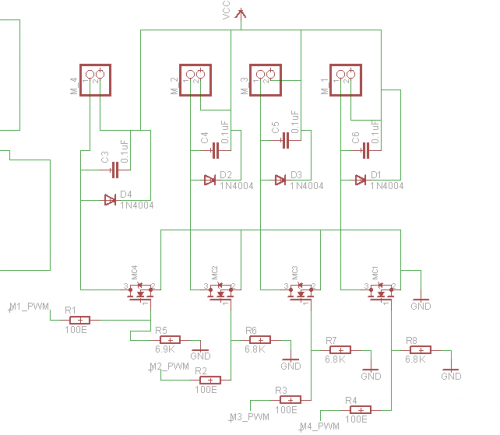
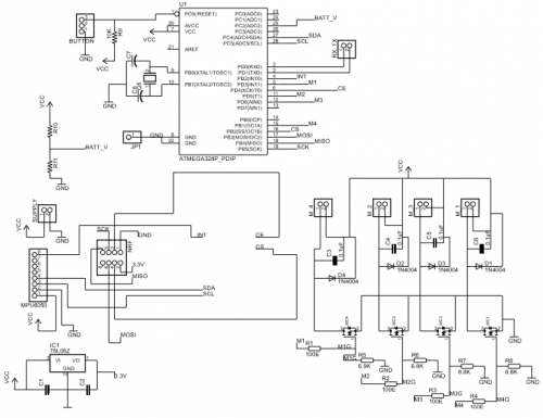
It uses an ATMega328 DIP package on a PCB. The motors I'm using are small coreless motors and I'm trying to control them using Si2302ds N-MOS FETs. For the power supply I'm using a 3.7V(4.2V on full charge) Lipo. I've tested this setup on a promini before and the motors turned on and off just fine.

This time I'm having problems with controlling 1 motor out of the 4. I've attached 0.1uF caps across each motor terminal (see schematic). Them control pins used for the motors are pins 3,5,6,9. The problem occurs at pin 3. I tried running the blink program on pin 3 to pulse the motor on and off through the FET but all I get is a bit of clicking from the motor.

Things I've already checked relating to the circuit :

  • FETs are soldered on correctly and made sure they aren't defective.
  • Motor works fine prior to connecting it to the circuit.
  • Disconnected the FET and motor from pin 3 and checked the output. It works fine on its own.

Is the problem occuring due to noise generated by the motor? What could be the problem? I've attached the schematic to this post. Thanks in advance :D

Screenshot__345_.png

Here is the code I'm testing. (Simple blink program)

#define motor1 5
#define motor2 3
#define motor3 6
#define motor4 9

void setup()

{
pinMode(motor1, OUTPUT);
pinMode(motor2, OUTPUT);
pinMode(motor3, OUTPUT);
pinMode(motor4, OUTPUT);

digitalWrite(motor1,LOW);
digitalWrite(motor2,LOW);
digitalWrite(motor3,LOW);
digitalWrite(motor4,LOW);

delay(1000);
}

void loop() {


 digitalWrite(motor1,HIGH);
 delay(10);
 digitalWrite(motor2,HIGH);
 delay(10);
 digitalWrite(motor3,HIGH);
 delay(10);
 digitalWrite(motor4,HIGH);
delay(10);
delay(1500);
 
 digitalWrite(motor1,LOW);
 digitalWrite(motor2,LOW);
 digitalWrite(motor3,LOW);
 digitalWrite(motor4,LOW);
 
 delay(1000);
}

Motor control

  1. When you mention pins are you refering to the CPU chip pin?
  2. Have you set the associated DDR in the code? 

Hey ggallant,1. The chips I

Hey ggallant,

1. The chips I mentioned are the digital ones (i.e Pin 3 would be the 5th pin on the physical package). Pin 3,5,6,9 are the pins with PWM.

2. I’m sorry but I don’t understand what associated DDR meant. I googled it and found this “a computer bus operating with double data rate (DDR) transfers data on both the rising and falling edges of the clock signal.” Did you mean this ?

I’m simply using the blink program for testing whether the chip can succrssfully turn the motors on and off using the DigitalWrite command. So far three of the motors are working fine but one motorat Pin 3 refuses to turn on and just makes a clicking sound.

Hey ggallant,1. The chips I

Hey ggallant,

1. The pins I mentioned are the digital ones (i.e Pin 3 would be the 5th pin on the physical package). Pin 3,5,6,9 are the pins with PWM.

2. I’m sorry but I don’t understand what associated DDR meant. I googled it and found this “a computer bus operating with double data rate (DDR) transfers data on both the rising and falling edges of the clock signal.” Did you mean this ?

I’m simply using the blink program for testing whether the chip can succrssfully turn the motors on and off using the DigitalWrite command. So far three of the motors are working fine but one motorat Pin 3 refuses to turn on and just makes a clicking sound.

What I would check.

Is the ATMega328 in a socket?  If so you can pull it out and spoof its output at the socket to see if its the chip or the socket.  

You can also swap motors to see if motor 3 works in the motor 1 circuit and vice versa.

You can make a simple logic probe from a led and resistor and check all the other pins when you think motor 3 should be working to see if you misread the pin assignments.  (It happens to everybody.)

Can you move the connection to a different PWM pin?  You don’t say if its a prototyping board or a etched board.

Check the traces and vias on the pcb.  Especially if you had someone else fab the board it could have a flaw short or open via.

Good Luck

RG

DDR

Data Direction Register. Determines whether an I/O pin is an input or an output. Some hardware functions and libraries will do this for you. If you are bit banging then you need to do it yourself. Perhaps post the code and we can be of more assistance.


Hey RG,The ATMega is in a

Hey RG,

The ATMega is in a socket. I put the chip back in the Arduino board and gave the outputs to the PCB as you suggested and it worked perfectly.So could the problem be that the chip on the PCB s underpowered ? Why would only Pin 3 not work ?

I’ve made this circuit on an etched board using toner trasnfer at home. Here’s a clearer sschematic of the motor connections as the earlier one I posted was not clear. I’ve connected all 4 motors identically so its really puzzling why only pin 3 malfunctions.

Screenshot__359_.png

Hey ggallant,The code I’m

Hey ggallant,

The code I’m running is just a simple blink program to test whether the chip can turn the motors on or off. I tested the same code by removing the chip from the PCB, then putting it back on the Arduino board and porting the o/ps to the PCB and all worked fine!

I’m guessing that it’s some underpowering issue then?

Check the socket.

Get out your magnifying glass and check the socket.  I have seen missing or damaged contacts.  Also check your soldering and resolder any connections that are suspect.  And resolder the suspect pin just to be sure.

That should fix it if its a bad solder joint.  If its a bad socket it will need to be replaced.

RG

Hey RG,I checked the socket

Hey RG,

I checked the socket using my DMM continuity tester and it didn’t show any bad connection between the pin and resistor. I still soldered the pin again but there was no change in the circuit. I even checked it with another chip just to make sure the defect wasnt in the chip.

When I try to switch all 4 motors on they dont come on (even the working ones). When I cut the trace of the non functioning motor, the other 3 work properly. I then tried connecting the pin and resistor through a external wire but then it shows the same result (i.e. no working ).

Is there some loading effect at the pin that causes the other motors to switch off too ?

Motor problems

  1. You are using the same Vcc to power both the CPU and the motors.
  2. There is only 1 cap from Vcc to GND (C1) and it does not display a value. Probably needs to be about 470uf.
  3. Post your code and we can duplicate a portion of your environment.


Hey ggallant,1. The whole

Hey ggallant,

1. The whole circuit is powered by a 3.7V (4.2V peak) 25C 500mAh Lipo. It works fine for powering 3 motors but is failing when I try to power one at pin 3(Even when that alone is the pin being powered). This caused me to doubt it being a power issue. I also tried the spoof test RG mentioned and all 4 pins worked fine.

2. The cap I’ve put is a 220uF electrolytic one. (Sorry for the unclear schematic) It is between vcc and gnd as you mentioned and is soldered close to the atmega chip. Should I add another 470uF ?? Or should I replace this with 470uF? The 220uF worked on a breadboard.

3. I have edited the original post with the code. Thank you so much!

I will load and test code,

I will load and test code, no motors or driver. Your schematic does not specify the crystal frequency but the 328 is not guarenteed to run at 16MHz at 3V. Are your promini’s 3V?

Hey ggallant,The crystal

Hey ggallant,

The crystal connected is of 16MHz. The promini was 5v one. I had connected the battery directly to the vcc pin bypassing the 5V regulator on the board. On the PCB I made the atmega vcc is also directly connected to the batterry. All the tests I tried were with the batter at 4.2V. Safe zone for 16MHz would be 3.8V and above right?

Thanks!!!

Vcc

Do you have a 5V supply? Can you supply separate power for CPU and motors?

I would suggest you add some serial print statement in both the init() and loop() functions. That way you can tell if the CPU is resetting.


Hey ggallant,I tested the

Hey ggallant,

I tested the code with the serial statements that you suggested and it helped clear the problem up alot. The atmega is restarting only when Pin 3 is activated. Any other pin on the board being switched on and there is no problem, but when I pull pin 3 HIGH the chip restarts.

Is this problem power related?? When I powered the chip from the arduino 5V and motors from battery all the pins worked fine, even pin 3. Why would it only be caused at pin 3?? Would i be a PCB trace problem??

I also took videos of the problem in order to make it clearer.

Here is a video of the board working when the chip is powered separately.

Here is a video when the board is continuously restarting when powered by battery only and pin 3 set to HIGH.

Thanks alot for your help ggallant!!

Not only the big capacitors…

Try to add a 0.1 uF cap over the 328 chip power pins. as close at the chip as possible. Those small caps do really help by filtering those little short power dips.

Another thing to look at is that your power wires should be soldered as direct as possible to your power supply and not via other wires/components. For example battery wire -> soldered on pcb by fet -> then another wire soldered at pcb to arduino power pin.

CPU reset

Try putting resistors in place of the motors. Start with a high value (500ohm) and work down. Verify that the reset condition is only on motor 3. If it is, it is time to test/replace the components in that path.

Note: For low value resistors you probably need the higher wattage types. Simple calculation. P = I x V or any other derivation using I,V & R.

Hey ggallant,I did this test

Hey ggallant,

I did this test on the pin the motor wasn’t working on and it worked fine until I reached 10ohms (lowest value I had).

Then I connected the motor in series with the resistor and it started to work. I checked the reisistance across the motors and it was between 1-2ohms. Is this causing some problemsfor the Atmega pins ? How come 3 motors are driven fine but it struggles with only this particular one ?

Also is it possible to isolate the MCU vcc from the rest of the circuit using a resistor ?

Thanks!

Motor drive circuit

Sounds like the system is resetting at 0.4A. Is this the same for all motor drive circuits?