

Lessons Menu:
- Lesson 1 – Software Downloading / Installing & Interface
- Lesson 2 – Basic Code
- Lesson 3 – Sensors: Potentiometers
- Lesson 4 – Sensor: Infrared Distance
- Lesson 5 – Actuator: Servo Motor
- Lesson 6 – Sensor: Force, Bend, Stretch
- Lesson 7 – Sensor: Accelerometer, Gyro, IMU
- Lesson 8 – Shield: Wheatstone Bridge & LCD
- Lesson 9 - Programming Arduino Platforms Using a Different IDE
Lesson 2 Hardware:
- Computer / Laptop or Netbook
- Arduino Microcontroller
- USB to Serial Adapter (if your microcontroller does not have a USB port)
- Appropriate USB cable (Arduino boards draw power from the USB port – no batteries yet)
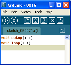
The Arduino language is CASE SENSITIVE: a capital letter is not the same as a lower case letter. The following code represents the minimum in order for a program to compile:
The “void setup()" section is widely used to initialize variables, pin modes, set the serial baud rate and related. The software only goes though the section once.
The “void loop()" section is the part of the code that loops back onto itself and is the main part of the code. In the Arduino examples, this is called "Bare Minimum" under File-> Examples -> Basics. Note that you are free to add subroutines using the same syntax:
void subroutinename() {}
Almost every line of code needs to end with a semicolon ‘;’ (there are a few exceptions which we will see later). To write single line comments in the code, type two back slashes followed by the text:
//comments are overlooked when compiling your program
To write multi-line comments, start the comment with /* and end with */
/* This is a multi-line comment and saves you having to always use double slashes at the beginning of every line. Comments are used used to explain the code textually. Good code always has a lot of comments.*/
Serial Communication
The Arduino board can communicate at various baud ("baud rates"). A baud is a measure of how many times the hardware can send 0s and 1s in a second. The baud rate must be set properly for the board to convert incoming and outgoing information to useful data. If your receiver is expecting to communicate at a baud rate of 2400, but your transmitter is transmitting at a different rate (for example 9600), the data you get will not make sense. To set the baud rate, use the following code:void setup() {
Serial.begin(9600);
}
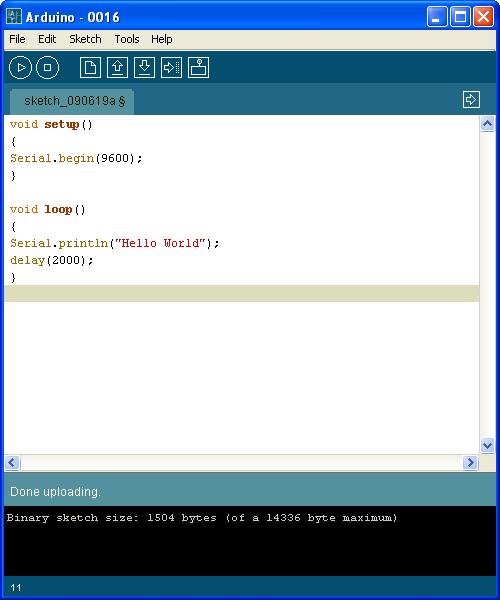
9600 is a good baud rate to start with. Other standard baud rates available on most Arduino modules include: 300, 1200, 2400, 4800, 9600, 14400, 19200, 28800, 38400, 57600, or 115200 and you are free to specify other baud rates. To output a value in the Arduino window, consider the following program:
Verify the program by pressing the “verify” button (looks like a “play” button in order version or a check sign in Arduino 1.0); you should not get any errors at the bottom of the screen. If you get errors, check that only the two numbers in the code are black, the rest of the text should have been automatically recognized and assigned a color. If part of the text is black, check the syntax (often copy/pasting text from another program can include unwanted formatting) and capitalization.
Next, upload the sketch to the board using the “Upload to I/O Board” button (arrow pointing right). Wait until the sketch has finished uploading. You will not see anything unless you then select the “Serial Monitor” button (rectangle with a circle that looks like a TV in the old software, or what looks like a magnifying glass in the new software). When you select the serial monitor, make sure the baud rate selected is the same as in your program. If you want to save all your programs, we suggest creating a new folder called “reference” and save this program as Hello World.
Blink LED Program
Connect the board to the computer if it is not already connected. In the Arduino software go to File -> Examples -> Basics -> Blink LED. The code will automatically load in the window, ready to be transferred to the Arduino. Ensure you have the right board chosen in Tools -> Board, and have the right COM port as well under Tools -> Serial Port. If you are not sure which COM port is connected to the Arduino, (on a Windows machine) go to Device Manager under COM & Ports.
Press the "Upload" button and wait until the program says "Done Uploading". You should see the LED next to pin 13 start to blink. Note that there is already a green LED connected to most boards - you don't necessarily need a separate LED.
Understanding Blink LED Code
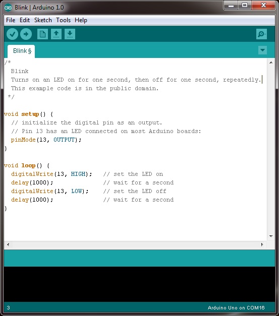
From Lesson 2 you will recognize the basic code void setup(){} and void loop(){}. You will also recognize the green commented sections. The three new lines of code you have not seen before are:
pinMode(13, OUTPUT);
This sets pin 13 as an output pin. The opposite, being INPUT, would have the pin wait to read a 5V signal. Note that the 'M' is capitalized. A lower case 'm' would cause the word "pinmode" to not be recognized.
digitalWrite(13, HIGH); and digitalWrite(13, LOW);
The line digitalWrite(pin, HIGH); puts a specified pin high to +5V. In this case we chose pin 13 since on the Uno, the LED is connected to pin 13. Replacing HIGH with LOW, the pin is set to 0V. You can attach your own LED using a digital output and the GND pin. Note that the ‘W’ is capitalized.
delay(1000);
The delay(1000); line causes the program to wait for 1000 milliseconds before proceeding (where 1000 is just a convenient example to get a 1 second delay). Note that during a delay, the microcontroller simply waits and does not execute any additional lines of code.
Special Note
Pin 13 incorporates a resistor with the LED, whereas none of the other digital pins have this feature. If you want to connect one or more LEDs to the other digital pins, you need to add a resistor in series with the LED.
This is a companion discussion topic for the original entry at https://community.robotshop.com/tutorials/show/arduino-5-minute-tutorials-lesson-2-basic-code-amp-blink-led