This is Ardubot, another Arduino based robot. Its base is the Sparkfun Ardubot. The brain is a Seeeduino V328 Arduino Duemilanove compatible board. Powered by a 7,4V 1100mAh LiPo battery. Motor Controller is the standard Ardubot L293D Dual motor controller. The wheels are the Pololu 42x19 wheels with quadrature encoders. The LCD on top is a DOGM163 16x3lines display. A PCF8574 I2C port expander has been used to limit the ports needed to control the display.
The main function of Ardubot for me is to serve as a test platform to develop hardware and software modules for reuse on other projects. So it must be highly configurable and easy to change its components.
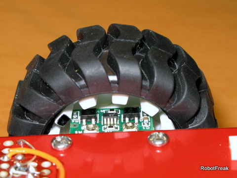
Quadrature encoder:
The picture shows the Pololu wheel with the quadrature encoders. 2 trim potis can be used to correct the output signals A and B. More infos at the Pololu site.
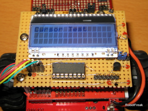
I2C LCD module:
The LCD module is a DOGM 163 3x16 character LCD from lcd-module.de. It is controlled in 4-bit mode. Because I am running out of pins a PCF8574 I2C port expander has been added to control the LCD via I2C bus. It takes some time to adapt the LiquidCrystal library for the PCF8574 and the DOGM module. I think this is a seperate Tip&Walkthtrough worth.
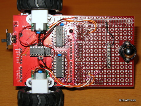
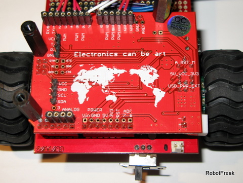
Downside:
A lot of wires and components are on the downside of the Ardubot base. The L293D motor controller, a second PCF8574 port expander for the line sensor (not shown) and a 74AC14 Hex Inverter chip. 2 inverters are used for the motor controller, spares 2 more Arduino pins. I don't like the way the motor controller has been connected to the Arduino board. So I cut all connections and make it my own (more flexible).
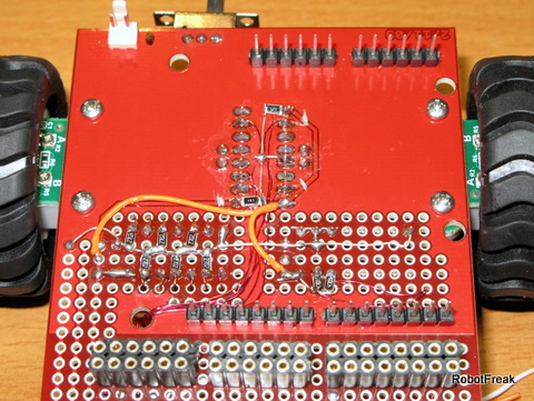
Upside:
On the Upside of the Ardubot you see the removed and rewired connections and a lot of SMD resistors. The resistors are neede for PullUp and Pulldown issues. So all inputs of the ICs have a default potential, when not in use. All in and outs of the ICs are connected to the female connectors in front. So I can choose between different hardware setups.
Seeduino V328:
The brain of Ardubot is the Seeeduino V328, an Arduino Duemilanove clone. I choose the Seeeduino not only for the colour (identical to the base board) it has some really cool features:
2 extra A/D pins
seperate connectors for I2C and UART
separate Arduino IOs with breadboard compatible pin spacing
works with 5V or 3,3V
selectable auto or manual reset
First Test 'write LMR':
The first test is a demonstration of the wheel encoders. The quadrature encoders give you 2 signals per wheel. With some fine tuning you get an almost perfect squared output with a 90 degree offset between the 2 signals. Per wheel revolution you get 48 ticks, that is 2.75mm for one tick. That is not so bad and can be easyly handled by the Arduino. I use a timer interrupt (1ms) instead of a pin change interrupt because it is simpler to use and gives you a better result. The video shows the result. Ardubot tries to write 'LMR', more or less succesfull. The result is not perfect, but this is more a software issue. It is not as easy as you may think to syncronize both wheels. Drawing the half circle on the letter 'R' is a real hardware issue. It is not possible with the L293 motor controller to drive very slow, as needed for the inner wheel. It just stops turning. If you drive faster (increasing the PWM), the half circle gets too big :-(
Further tests:
line sensor
proximity sensors
IR remote control
I2C LCD
Tries to write 'LMR'
Actuators / output devices: 2 x 1:100 Pololu micro motors
I use the enable pins of the L293D for PWM already. The problem is that the inner wheel starts moving only at a PWM value of 80 or higher. The outer wheel runs with full speed. There is a gap between the small circle (inner wheel stops) with 9cm diameter und when the inner wheel starts moving. Resulting in a diameter of 20 or more cm. So i cannot draw a circle with a 15cm diameter for example.
Maybe a battery with higher voltage may solve this behaviour or another motor controller.
I recently bought this encoder but I am not familiar with using encoder. This is the first time I try to use it. I notice there are 4 soldering spot on each encoder. May I share the power source(Gnd,Vcc) to these 2 encoders? Are they using 4.5~5.5V? If I use 7.4V, can I use 7805 regulator to lower the voltage? Another OUTA and OUTB spot, do I connect it to digital pin or analog pin?
I have download the library but not so sure how to code it. You have any sample code to read them? Thanks a lot for your time and the post.
Great platform, lots of useful stuff to play with there. I’m hoping to dabble with Arduinos rather than PICs for a while and may be treading in your footfalls. Excellent stuff
If you want to try something that’s a bit of both, why not take a look at the chipKIT platform options?
They’re compatible with Arduino shields and use a modified Arduino programming environment (USB-based bootloader-style programming), but you get the power of a 32-bit PIC controller and you can still use MPLAB or any other PIC programmer you like instead, as there’s still a header for attaching a PICkit/etc.
I picked up one myself a few weeks back and so far I’ve been really happy with it. The project I’m working on might need to be copied a few times, so I decided it was a good time to buy an “off the shelf” development board =)
I’m just wondering if after 2+ years it was helpful in development as Robotfreak intended. It’s amazing how sometimes bots here don’t get the response they should when posted which I guess can be discouraging. But this little baby looks a very good step up from a start here robot.
OUTA and OUTB are the quadrature encoder outputs. These are digital outputs so connect them to digital inputs on the Arduino. VCC is 5V. the WriteLMR sketch is using the encoder library.
Funnily enough, I only stumbled across Chipkits yesterday and they look to have a powerful processor to play with. So much to learn and not enough time !! Being able to use sheilds allows some complex functionality to be built up while using a powerful processor.
I know this was a long time ago for you but I’m intersted to know what kind of accuracy you found when using encoders and odometry. I see from the video you had a pretty accurate means of writing LMR, but I guess the error becomes cumulative and it may be necessary to reset and start again.
Just wondering if you had a feel for how useful counting wheel rotations was for determining the robots position ?
the encoders used here give you a resolution of ~3mm/tick. Using encoders will always give you some error that will increase with the runtime. Think about slippage of the wheels or the inaccuracy or the value distance/tick. The program code I use here is not perfect. I don’t use PID control or floating point math here.
You will need a second sensor (laser scanner, 3d camera) do determine the robots position in a room.
Thanks for the reply, that is interesting info about the encoders. I’m very interested in localization and mapping and when I upgrade my robot to free me from the raw hardware control, I’m definitely going to investigate further. I’ve come across SLAM before but confess the mathematics and particle/Kalman filtering looks a bit daunting but i guess when you need to work it out, it will come ! Thanks for the link, that looks a great place to start trying to understand SLAM and the whole mapping/localization problem in general.
BTW, I like your other bot that is using the phone for the main processing platform. Having a computer with plenty of RAM will give you a lot of scope to look at Higher-level navigation algorithms which is an area I want to investigate.
However, I need to walk before I can run and will slowly slowly catch the monkey. I need to modify my basic robotic platform first and when I am a little wiser, it will be time to dive into the complexities of some of the navigation algorithms.