


Ardubot, robot test platform
This is Ardubot, another Arduino based robot. Its base is the Sparkfun Ardubot. The brain is a Seeeduino V328 Arduino Duemilanove compatible board. Powered by a 7,4V 1100mAh LiPo battery. Motor Controller is the standard Ardubot L293D Dual motor controller. The wheels are the Pololu 42x19 wheels with quadrature encoders. The LCD on top is a DOGM163 16x3lines display. A PCF8574 I2C port expander has been used to limit the ports needed to control the display.
The main function of Ardubot for me is to serve as a test platform to develop hardware and software modules for reuse on other projects. So it must be highly configurable and easy to change its components.
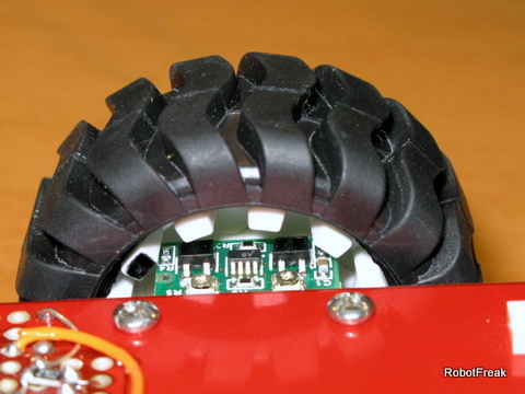
Quadrature encoder:
The picture shows the Pololu wheel with the quadrature encoders. 2 trim potis can be used to correct the output signals A and B. More infos at the Pololu site.
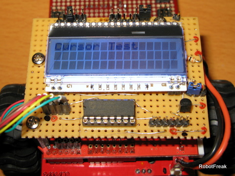
I2C LCD module:
The LCD module is a DOGM 163 3x16 character LCD from lcd-module.de. It is controlled in 4-bit mode. Because I am running out of pins a PCF8574 I2C port expander has been added to control the LCD via I2C bus. It takes some time to adapt the LiquidCrystal library for the PCF8574 and the DOGM module. I think this is a seperate Tip&Walkthtrough worth.
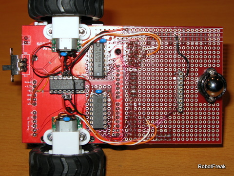
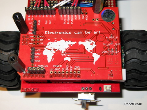
Downside:
A lot of wires and components are on the downside of the Ardubot base. The L293D motor controller, a second PCF8574 port expander for the line sensor (not shown) and a 74AC14 Hex Inverter chip. 2 inverters are used for the motor controller, spares 2 more Arduino pins. I don't like the way the motor controller has been connected to the Arduino board. So I cut all connections and make it my own (more flexible).
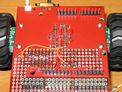
Upside:
On the Upside of the Ardubot you see the removed and rewired connections and a lot of SMD resistors. The resistors are neede for PullUp and Pulldown issues. So all inputs of the ICs have a default potential, when not in use. All in and outs of the ICs are connected to the female connectors in front. So I can choose between different hardware setups.
Seeduino V328:
The brain of Ardubot is the Seeeduino V328, an Arduino Duemilanove clone. I choose the Seeeduino not only for the colour (identical to the base board) it has some really cool features:
- 2 extra A/D pins
- seperate connectors for I2C and UART
- separate Arduino IOs with breadboard compatible pin spacing
- works with 5V or 3,3V
- selectable auto or manual reset
First Test 'write LMR':
The first test is a demonstration of the wheel encoders. The quadrature encoders give you 2 signals per wheel. With some fine tuning you get an almost perfect squared output with a 90 degree offset between the 2 signals. Per wheel revolution you get 48 ticks, that is 2.75mm for one tick. That is not so bad and can be easyly handled by the Arduino. I use a timer interrupt (1ms) instead of a pin change interrupt because it is simpler to use and gives you a better result. The video shows the result. Ardubot tries to write 'LMR', more or less succesfull. The result is not perfect, but this is more a software issue. It is not as easy as you may think to syncronize both wheels. Drawing the half circle on the letter 'R' is a real hardware issue. It is not possible with the L293 motor controller to drive very slow, as needed for the inner wheel. It just stops turning. If you drive faster (increasing the PWM), the half circle gets too big :-(
Further tests:
- line sensor
- proximity sensors
- IR remote control
- I2C LCD
Tries to write 'LMR'
- Actuators / output devices: 2 x 1:100 Pololu micro motors
- Control method: Infra Red
- CPU: arduino 328
- Power source: 7, 7.4V 1100mAh LiPo
- Programming language: Arduino
- Target environment: indoor