I saw this code about Neural net on an Arduino here: http://robotics.hobbizine.com/arduinoann.html
and would like to know how I could apply it to my latest robot DuckBot so that it could figure out how get back on it's feet
on it's own instead of me having to code explcitely to do that. I have one sensor that currently says if angle of sensor indicates < 145 degrees then robot has fallen. It uses 3 servos to get back up on its feet.
Any ideas greatly appreciated.
DuckBot with Neural Net Learning
Count me in. Been meaning to make a DuckBot ever since I saw your videos. Are you tkinking about a complete learning system where when it falls it just flops until success or some sort of assisted algorithm where it fine tunes the process? Some questions:
- How to store the learning history so that it survives a reset?
- What sensors?
- Limitted to Arduino?
I think the ultimate would be 1 or more baby DuckBots inheriting basic skills and getting “help” from the mother DuckBot.
There are endless variations to this scheme. Why not apply the technology to walking, talking, sleeping?
Hi Ggalant - that’s great. I
Hi Ggalant - that’s great. I will be a little late in replying as I am in China and so on the wrong side of the clock from you if you are in US.
I will answer your questions later as I have to run to class in a few minutes. But from your questions I can say that my aspirations are a little meager - I just want to see how to use Adruinoann, if possilbe, to use a few canned movement routines to get back on its feet. I am a poor programmer (got kicked out of C forum one time for that reason) and not too good at fabrication. Just curious mostly.
Jim.
Ok to answer some
Ok to answer some questions:
I want to do something as simple as possible at first - just to see how to implement the algorithm about which I know absolutely nothing. So I was thinking of reading and using the servo positions as inputs, but perhaps limiting them to few basic servo positios in functions like: onTheRightSide, onTheLeftSide, onTheBack, onTheFace and then use the output servo positions to move to and use the SCA60C sensor angle to determine success. I want to use theArduinoAnn code if possible for a trial experiment cause I don’t want to write anything from scratch.
It didn’t even occurr to me that we have to store output to history or it gets lost when the Arduino powers down. So for an initial try it would rerun the algorithm every time it was reset - that would be fun to watch anyway and it would simplify the program.
I want to limit my initial experiment to the arduino if possible because I just want to get my toes wet and see where it takes me.I know that memory is an issue so the program can’t be too involved.
I have looked at the ArduinoAnn code just a little but I don’t know yet how to integrate the sensor and servo data into the input and output arrays. If you have any knowledge of how to accomplish that, that would be great. I suppose I should just load up the program to an Arduino and play with it a bit. Or if you know of a good tutorial on neural nets I would appreciate it. I will search the web a bit and see what I can find.
Finally, I am not the sharpest tack on the board so don’t expect much from me except stupid questions. I agree you could go very deep and in a lot of directions with this type of inquiry but I’m just a sloppy tinkerer and would be happy to see the Duckbot get on it’s feet using its own cogitations.
Jim.
DuckBot
I had this idea yesterday to create a LMR contest usung 2 DuckBot’s. The first would be the Mother and the second (smaller) would be the chick. Place both in a 2 meter square arena and have the mother travel a path from nest to food to water and have the chick follow. Mother would have an IR beacon. Each station would have a trip switch that must be hit or stepped on. Add obstacles as needed.
Chatted with Dickel yesterday and he is interested. IMO, his fabrication skills complement nicely your creative skills. I am willing to make a 3d model that could be fabricated out of polystyrene (or other material) using glue and screws. The shapes would be laser printed on gloss paper and transfered to the plastic via iron. Same techinque as Iron-On-Transfer for making homebrew PCB’s. This would enable LMR members to make relatively standard Ducks. We could supply part numbers for the electro mechanical components.
If you are interested please reply with images of DuckBot next to a measuring stick and supply some basic measurements. Scalling for chick might require some experimentation. I know a “mass” produced DuckBot will look inferior to your original but I have confidence that Dickel will do it justice…
Hopefully someone from RobotShop is monitoring this forum and will comment.
What a cool idea! I will do
What a cool idea! I will do pictures tomorrow. I am sure it could be designed much better. The standard servo could be replaced with a microservo, the UNO with a Nano the battery pack with a 7.4 lipo, lots of ways to lighten and extend play time and make it smarter. The mom and chick obstacle course sounds like great fun.
Micro Server
As for designed “much better” I must disagree. By micro servo do you mean the 9G units?
The current design uses 2
The current design uses 2 six volt 9 g servos for the legs. They are about at their max capabilities - that is why to get it back on its feet after a fall, I have to swing the neck to the side first to get some weight off the opposing leg and to keep it from falling forward. Some 7.4 volt 9 gram servos would probably make the neck swing unnecessary and they would be strong enough to do some additional interesting duck movements (like sit on its butt and get up directly from that position).
I use a big heavy standard servo for the neck and that could probably be replaced with a 9 gram servo - I think it would be strong enough to swing the neck. And you are thinking to scale things down for the chick - the body is mostly an empty box that could definitely be shrunk down. Probably could use 5 gram servos for that if the power sources were shrunk accordingly.
Also, the feet may need some padding as it walks fine on a wooden table top but tends to fall occassionally on stone or ceramic floors - I think it is actually getting some dampening from the flexible wood table.
Just musing. By the way I am probably about 12 hours different than you so won’t always respond very timely.
Photos of Duckbot and measurements…
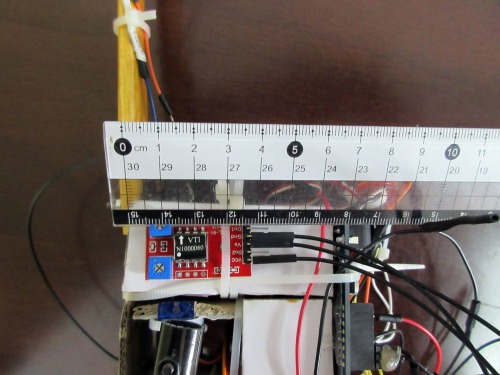
Body is 7cm by 7cm by 4cm.
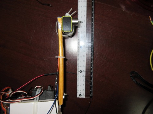
Neck is 13cm from servo shaft to end of neck.
Legs are 8.5 cm long and 6.5 cm from bottom of foot to servo shaft.
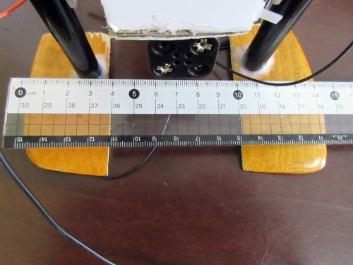
Feet are about 14.5 cm from outer edge of foot.
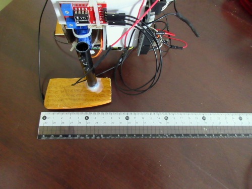
Feet are 8cm long and center of leg is about 2.5 cm from back of foot.
Center of Mass is just behind the leg servos.
Actually body measurements
Actually body measurements are 7cm long by 6.5 cm high by 4.5 cm wide.
Measurements
Thanks. I have been working on a 3d model in openscad. Some pictures have something (I think) like a battery case hanging below the body. I’m assuming the voltage regulator is for servo motor power.
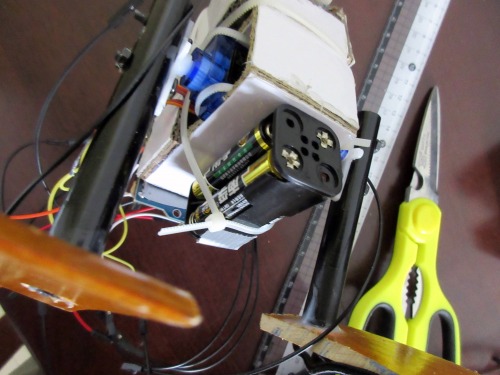
The battery pack below the
The battery pack below the body is 4 AAA batteries that run the servos directly. I don’t have to use a voltage regulator. They also serve as a counterweight to keep the duck balanced. The module on the side of the body is the SCA60C tiltmeter sensor and serves to indicate if the duck has fallen or not. The 9volt that serves as the head runs the Arduino Uno and also serves as a counterweight. Got that idea from Fritz’ 3 servo robot duck.
Pic of AAA battery pack that
Pic of AAA battery pack that runs servos.
.
Balance Question
Are the feet or legs not at 90 degree angles such that when the weight is shifted the feet are flat on the ground?
Yeah, sorry I forgot as that
Yeah, sorry I forgot as that is pretty important. The feet are canted a few degrees from the inside to the outside. The inside edge of the feet are flat on the ground but the outside edge is about 5 mm off the ground.
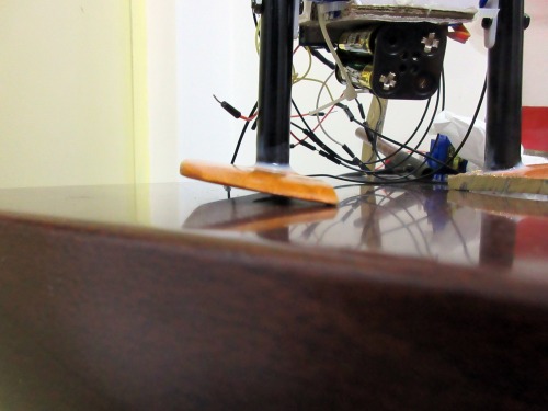
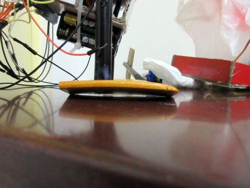
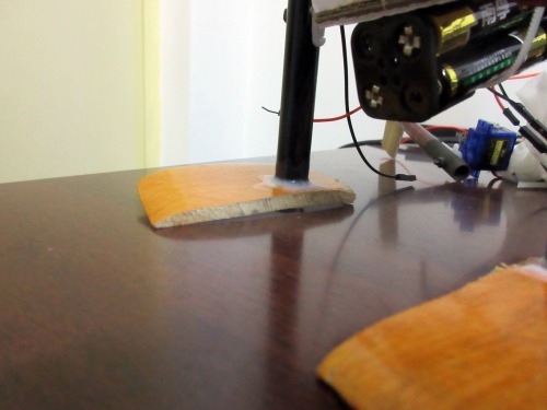
One more design feature I
One more design feature I didn’t talk about but you may have observed: there is space in front and behind the leg servos so they can be slid front and rear to achieve a good balance point - then they are locked down by the two cable ties that hold them in to the body. When I first built the duckbot I had the servos all the way forward and it would fall over backward a lot so I was able to deal with that issue by sliding them back.
Some pics
Balance I suspect required your skilled adjustment skills. Attached are a couple of pictures of current 3d build from dropbox. I have not been very successful with pictures and LMR so please comment if they are not found. Not nearly ready for production.
Looks pretty cool. Would be
Looks pretty cool. Would be wonderful if it didnt have to have all the ugly wiring and could just be nice clean components like your 3d. Rock on!
I have to go entertain a bunch of college students today - it doesnt hurt that they are beautiful. Too bad I am so old.
Current consumption
Any idea on the max current required to operate DuckBot? I think you wire the 4 batteries to the motor power.
It needs 6 volts to power
It needs 6 volts to power the servos. 5 volts won’t quite do it. Can’t go any higher than 6 volts unless you use a higher voltage servo with are available and not that expensive.


