4WD Rover - my first robot in progress

This is my first autonomous 4WDBOT on a DfRobot Base.I try to keep all mountings as clear and functional as possible - no decoration parts.

Update:
After some code-tunings the obstacle avoiding system runs fine now - even with higher speed. I've implemented a speedboost-mode if the distance is higher as 200cm, so it much faster on larger distances. There is a new video online with the second obstacle avoiding test.

Update:
Success! Even there is a lot of finetuning with gears and delays to do it is really nice to see the bot running! There is a new video with the first obstacle avoiding test.

Update:
All sensors and motors are running great now. I got clear readings. Everything is hooked up nicely and the sensorhead reacts on lightconditions just fine. I can read the light on the left and ride side now with values between 0 (darkness) and 255 (bright sunlight). The URM gives me now smooth values between 5 and 300 (cm). Maybe I can start the first autonomus tests today. It evaluates three variables - front distance, left distance and right distance. It should be possible now to make movements because of different lightconditions and front/left/right distances. The code is cleaned up and commented out - but here is still a lot to do (there ist enough codespace free on the chip).

Update:
A new URM arrived. It's working just as it should be! Great! Yippie! I got a full range between 0cm and 280cm. In the meantime I had enough time to rearrange nearly every cable twice...  A nice little green plug-backpack is ready, too.
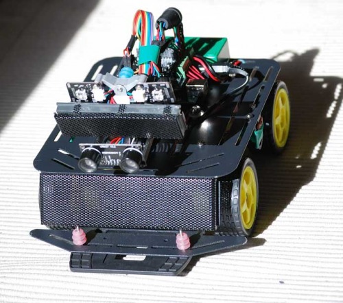

The mounted URM sensor
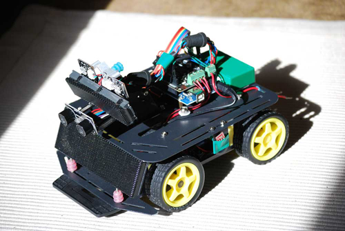

Better cable layout with a cleaned out cable backpack
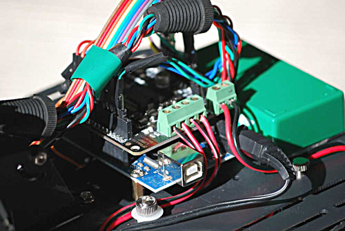

Thumbscrews for cable holdings, antishake cable holder, vibration damper now everywhere...

Update:
At the moment I am working on the ultrasound navigation. I am not sure if my URM3.7 unit is broken - I can read the values over Rx + Tx but the measurement range is only between 4cm and 10cm. It should be between 4cm and three meters. I am using Miles Burtons URM library with Arduino 2.2 wich is originaly written for 1.7. Or I have to put the URM in another Mode over serial - I am not sure at the moment. If somebody here has got a good idea because of this strange behaviour I would be glad to hear it.
 

URM Update: The URM3.7 is destroyed - two of the capacitors on the back are missing. Maybe because of a weak solderingconnection? Maybe because of my fault? Who knows. But finally I have found the error and I can reorder a new part. Maybe is possible to fix it - but it's smd size and really small.

Update:
Today I have soldiered the cables to the two lightsensors and rearranged the cable layout. Maybe I will multiplex them later to eight - but at the moment two sensors are good (left side + right side). Additionally I have prepared the front for two speaker, for hyper hifi stereo. I have just ordered my second URM - and I've found a nasty little analog alcohol-sensor for 4€. Ordered.

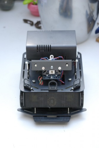
The black box on the back is a 12V batterybackpack. It is planned to place a solar-cell on the back for autonomous power charge. There is still a lot to do, but I'll try to submit pictures of every stage of the building process. I hope you like it. Comments, suggestions and help are much appreciated.


Alpha
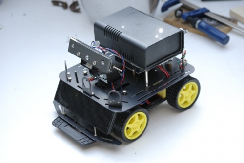
Sensorhead preview and batterypack mounted...
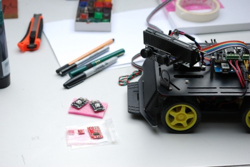


Light sensors, sharpies and 3W Stereo Audio Amplifier...

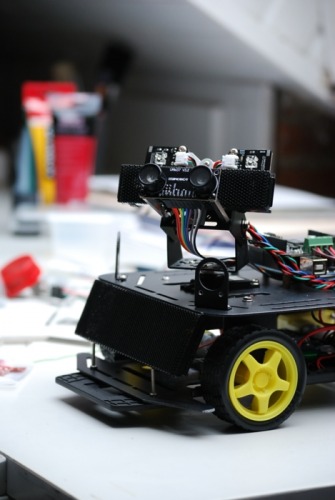
The sensorhead with the URM3.7 and sharpies mounted
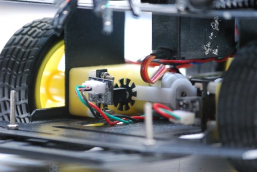
Rotary encoders mounted
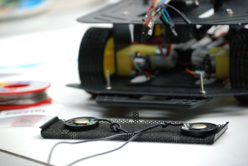
Preparing Stereo Audio in the perforated metal plate front (dustblocker)
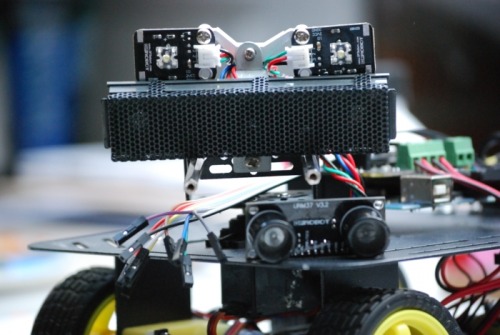
Face with unmounted URM (arrrgghh!) - rearranged, cleaner cable layout... the perforated metal plate is for the hidden white LEDs - otherwise you would not see it's eyelights at daylight.

Update:
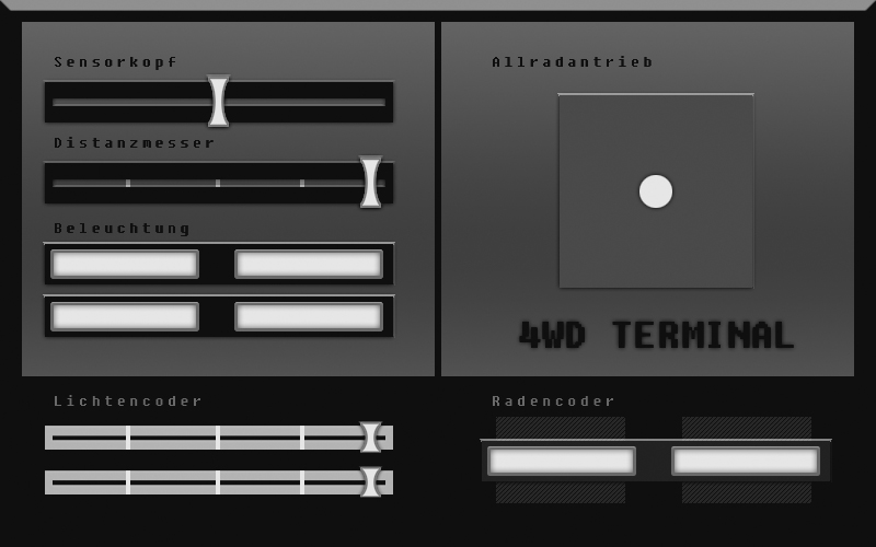
First pictures of my processing controlterminal for sensor- and encodertests


Ultrasound navigation, reacts on nearfield bodyheat, detects light

  • Actuators / output devices: 4x 1:120 gear motors (12V) 1x Graupner Servo
  • Control method: autonomous
  • CPU: arduino - atmega328
  • Power source: 12V Battery
  • Programming language: Arduino C
  • Sensors / input devices: 2 x light sensors, 1x URM37 ultrasonic, 2x rotary encoders
  • Target environment: indoor flat surfaces

This is a companion discussion topic for the original entry at https://community.robotshop.com/robots/show/4wd-rover-my-first-robot-in-progress

wow it looks so cozy cozy,

wow it looks so cozy cozy, post a video of it action too!

I have just uploaded a video

I have just uploaded a video of the geartest…

I got the URM37 running just tonight

Also with an Arduino, and my readings are perfect.
Make sure you set the URM to TTL serial, NOT RS232.
Also, there is a jumper in the middle of the module, also on the back, break that connection.
If you share your code I can have a look if you want?

I’m working with the same platform by the way! 

URM 3.7 strange sensor readings

Hi Benji, thanks for your reply.

The URM is set to TTL correct (like in the yerobot URM manual ). The two jumpers above pin 7+8 are triggered to TTL.
The third jumperconnection in the middle is open. I am using Miles Burtons library with the samplecode included. The code compiles well, I have a stable serial connection and I get distance values. I suspect to get values between 0 - 300 (1cm raster on three meters). But I get only values between ca. 6 - 15. Do I have to enable a different mode with the helpmate, maybe? Do you have switched modes with the helpmate? Could we compare the pinsettings, please? Thanks!


Test-Pinsetting URM3.7 to Arduino


  1. 5v - to Arduino 5v
  2. GND - to Arduino GND
  3. Reset - free
  4. PWM - free
  5. MOTO - free
  6. COMP / TRIG - free
  7. ON - to Arduino Pin 13-HIGH
  8. RXD - to Arduino Pin 3
  9. TXD -  to Arduino Pin 2


I’m using a URM37 V3.2 on my

I’m using a URM37 V3.2 on my MASHR robot, same setup (except Pin7) , same lib from Miles Burton. It works with no problem. Only difference I see is the ON Pin (Pin 7 URM32). I don’t use this pin. I’m using Mode1 (Serial passive control mode), Jumpers in TTL mode. Don’t remember, if I had to program the mode into the sensors EEPROM.

Did you test the sensor reading with disabled motors and without servo moves?

You can compare your code with my MASHR’s code

BTW. nice robot. The 4WD seems to work very well.


Try and wire the ON pin to

Try and wire the  ON pin to 5V, that works perfectly for me.
I get readings well over 150 cm, longest I’ve seen is 203cm.

Bug found - URM3.7 is destroyed

A black day for my bot - it still has to remain in blindness. Thanks for your help, but I have just checked the code and compared all resistors with the photo in the manual - and one of the resistors on the backside is destroyed. It is really micro - but you can see it clearly. Damn. This hurts. Bug found. Part destroyed - and reordered. Ashes to ashes.

And I am just sneeking

And I am just sneeking through your MASHR Code. Looks really fine - thanks!

Thanks Benji, but the part

Thanks Benji, but the part is destroyed.  It’s already reordered…

That’s a shame man, but it

That’s a shame man, but it does explain a lot.
That is why I always check every board or PCB I buy against the schematic, so i can see if something is wrong.

Good luck with the new part, you’re doing more with the chassis compared to mine at the moment!

It’s looking good!

You eliminated the wire mess I see, nice job!
Gotte work out some kind of cable management myself as well, though with the board I soldered it’s already a alot better.


I had a new test tonight, it

I had a new test tonight, it runs even more beautiful than it already did, so I’m getting there.
How did it go for you? 

I had some first tests tonight - epic fail :smiley:

My first test tonight wasn’t such a great success - everything is up and running now and all components work, but the delays are just terrible. The bot stops and turns - just after it hits the wall :smiley: I think I have to rearrange my messy code. I am not sure at the moment when it is time to take a measurement. My plan is: Get a measurement in centimeter, move the wheels, count the rotary encoders (1 turnaround = 18.85cm) then stop. Theoretically it is working - but pratically it hits the wall. Is it possible to compare some code with you?

It’s looking good :slight_smile:

It’s looking good :slight_smile:

I can publish my code

I can publish my code tonight, but it’s not ideal.
I don’t have encoders so that won’t help you.

I’m running my motors at not even 50% capacity at the moment while testing, and then I have about 10cm margin between bot and wall, when I set the stopping distance at 30 centimeters.

Simple flow:
Drive forward
Do measurment
When distance <= 30
Readsweep
Get reading at 0, 45, 90, 135, 180 degrees
Compare new distance to max distance
If new distance is higher than max distance, max distance = new distance, store angle
Turn to angle with most distance
get reading
if >= 30
drive

that works fine for me for now, I just need to figure out my turning routines since the 90 degree turns are about 100 degrees now, so tweaking to do.

As I said, I don’t have the encoders, so I need to rewrite a bunch when I can get those.

Thanks Benji!

Thanks, Benji. This helps me a lot. I have compared your lifecycle with mine and the MASHR code (thanks again for this nice piece of code). It is working way better now -> Success! There is still a lot of finetuning to do, but it’s working!

No problem, no effort at all

No problem, no effort at all :slight_smile:

now show us some video’s man! :wink:

It’s alive!

Nice work! :slight_smile:

It seems a bit jumpy still, but you’ll get it figured out!

Yes, it’s alive! And its beasty!

After some work it runs much smoother now - even with higher speed :smiley: