360bot - Stepper motors are cool!

Strange, some Google videos are down. Link to the one down now when writing this, here.

Update:

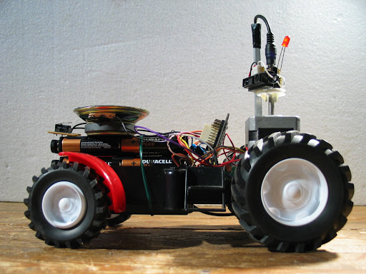
So I thought; With 360 degrees overview, I am unbeatable, I can navigate anything. I took an old toy-tractor and in amazingly short time got everything fitted onto it. That tractor was made for this, I thought.

I knew that it would be crap at steering, as the wheels where big, and the rear wheels (or front sometimes, this is 360!) where locked to each other, giving no differential steering, and slow turns.

But after a short while I got really tired of it; It is turning not on a plate, but on a big football stadium! :)

So it is going to die now, 360bot will not be on a tractor. Still I thought it looked cool :D And so I took some snaps just before I now go back and tear it apart. Click on image for more images..


Update:

I wanted to transfer power and signals to the moving part. I tried all sorts of stuff, but did not relly manage. So in the end I just gave up and used a 3.5mm jack-stick. Simple and easy.. but only 3 lines open.. So i had to give up on my first thought of having several LED's spin around. The thought was that they should sort of draw a rotating "radar image": Closer objects would make LED's closer to the axle light up.

However, I really like the sound of it spinning, and I will make something up! Added new video with the jackstick-trick. The LED on it is simply using the Sharp signal directly - that is actually quite a nice hack in itself :) I will always add a LED on the sharps from now on, nice indicator!


For a long time I wanted to hook up a stepper motor, and finaly I got to it!

Wow, these are cool! I enter this as a robot because I simply have to make a robot with this. I do not have much time, but now I have told you all that I am going to make a robot with a stepper motor, and so I will have to find the time :)

So far just a Stepper motor hooked up!

  • Actuators / output devices: 1 Stepper motor

This is a companion discussion topic for the original entry at https://community.robotshop.com/robots/show/360bot-stepper-motors-are-cool

i’m really glad to see

i’m really glad to see someone do somethign with steppers. These motors are soooo cool. Very versatile and easy to control…very accurate and torquey and teh different stepping modes (half/full/double step) make it very versatile and good for different situations, sacrificing accuracy for torque (rather than speed).


The only downsode for steppers is that you will usually need a seperate circuit to drive them (the microprocessor will only supply the triggers)…and you must be very careful as they swallow up huge amounts of current, and you need to use soem pretty high-grade resitors with them.


I’ve had cases where the resistors generate so much heat that they melt the surrounding wires…so be cautious!


Nice. I’ve always been

Nice. I’ve always been curious how fast a stepper motor can spin. Floppy drives were spun by stepper motors, weren’t they? The electronics store downtown has a ‘grab bag’ with 4 or 5 random stepper motors for about $25. I’ve considered picking one up to play with them, but I’m not sure if that’s a good price or not. They sound fun though.

Dan

The “grab bag” sounds very

The “grab bag” sounds very fair. I think I gave $25 for one. And I think you want as few amps and ohms as possible unless you want to drive something with it - I just like it to turn. Apart from (and including) this, I have no clue.

I just hooked it up to a standard 28 picaxe board, no special H-Bridge or anything. It says 12V, but I give it 5, and do not feel much difference if I give it more. It has 4 “signal” that I feed 2 by 2 with pause between, and 2 “Volt”, that I have just short circuited and give both 5V.

I may learn some more and tell about it. For now I am looking into making some sort of cool radar with it. I think :smiley:

Steppers R us

In work, my colleague and I have just completed a stepper driver. It drives a 4-wire motor 50 steps per rev with 64-microsteps per step. Get this: it has feedback using a Rotary Variable Differential Transformer. My colleague did the electronics (three H-bridges: two for the stepper and a third for the RVDT excitater. I did the software (including PID) in an FPGA. It took us nearly 8 months, but it’s a sexy piece of kit.

Guess what? He’s one of the ones who couldn’t explain FETs ina language I understand. Maybe I’m just thick?

I don’t understand why you’d
I don’t understand why you’d need an H-Bridge for the steppers. Can’t you just reverse the firing pattern on the steppers’ input pins?

That is what I do.
That is what I do.

Excellent Question

Indeed. The H-bridge is used for controlling the currents through the coils in both direrctions while micro-stepping.

Rather than pulsing each of the coils on and off in sequence, they are actually fed with a pair of out of phase sinusoidal currents . This means that even though the stepper only supports 50 steps per revolution, we can microstep, giving us a resolution of 0.1125 degrees!

Told you it was a bee-atch!

So you are saying that you
So you are saying that you first atract the thing like "normal"… but instead of atracting in a row, just in between each attraction, you push away from the one leaving?

great idea!

I absolutely LOVE the idea of the jack plug!!!


makes wonder why i never thought of that myself and always tried to consider complicated (high-noise) bearing and brush connections!


I’m really starting to love this site…a true testament to KISS :wink:

Sort of

I’m saying tha instead of switching the “attraction/repulsion” on and off, you ramp it up/down gradually. But in addition to that, yes, the current reverses so that the permanent magnet gets pushed away. I thikn your solution probably doesn;t do any pushing - only pulling.

Oh, got ya! I was
Oh, got ya! I was considering pushing as well, but it would take too many in/outs, and not really be worth it. Gradually! Smooth! :smiley:

More torque

It gives more torque because you have both coils energised instead of just the one. Like I say, this has been in the lab for a loooong time with two of us working on it nearly full time. Not to mention a professional team of support engineers to call on.

Don’t try this at home, kids.

(The last “S” would be me :slight_smile:

(The last “S” would be me :slight_smile: But I try to use it to my advantage :smiley:

And you are not the only one to consider brushes etc. I got this far before quitting :slight_smile:

Random stepper motors
If you want something cheap and aren’t too particular you can usually find decent stepper motors from surplus dealers. A few months ago there were even some small stepper motors somewhere for $.50 each. BGMicro had some excellent motors for $2.75 (instead of $8 from Jameco) but they sold out. Actually, most of the surplus sites seem to be out of good stepper motors right now, so it could be a good deal if they are big or high quality motors.

Beep and fart

Don’t give up! You are sooooooo close. cut eh back axle and mak teh stepper power only one of teh wheels. Get a brass gear servo instead of aplastic one for the steering. This could be so cool.

BTW - I love the video. Specially the bit at the end where the pile of sticks falls over and the small child laughing.

PS - why does everything you make have to beep and fart? Next I suppose it will be bashing stuff and recording the sounds it makes?

Howto wanted :stuck_out_tongue:

Hello, i have two spear steppers laying around, taken from an old broken printer. One of them looks exacly like the one you used.

I’d like to use them, but i’m completely clueless about how to control them… Why don’t you write a nice tutorial fritsl ? :stuck_out_tongue: Soemthing like “how to use a stepper with a picaxe board” :slight_smile:

I am not going to make a

I am not going to make a tutorial on this one because:

A) I have other tutorials waiting for me already

B) I neither have a clue :smiley:

However, here are my instructions, if all is 100% like mine, this will work, it is straight off the picaxe site, you may want to use high/low instead of “let pins”, if you are using other 4 pins for something:

’ If you use the wires in the 6 pin connector
’ order the following program will cause rotation
’ Black +12V
’ White +12V
’ Yellow output7
’ Red output6
’ Brown output5
’ Orange output4
main: let pins = %11000000
pause 10
let pins = %01010000
pause 10
let pins = %00110000
pause 10
let pins = %10100000
pause 10
goto main

Oh - and Wikipedia had some nice notes on how they work in general :slight_smile:

for maximum torque i’d

for maximum torque i’d suggest using the following pin sequence:

11000000

01100000

00110000

10010000


If you’re looking for less torque and more accuracy you can use the following:

10010000

10000000

11000000

01000000

01100000

00100000

00110000

00010000

Outside the Box

I’ve never tried this, but what are the merits of the sequence

1110

0111

1011

1101

In the case of a 4-coil motor this means that two of the coils are pulling against each other, but would there be any torque benefit?

Here’s another thought: You could compromise with a mix’n’match of torque and accuracy:

1000

1100

0100

0110

0010

0011

0001

1001

When the two coils are energised you have more torque (not double the torque, just “more”). You still have accuracy with the single coil steps, but the step might not be fully complete under high torque.