


axe020.pdf (200273Bytes)
Please note: The info on this page is about a board. However, things can be different depending on which chips you stick into the sockets of that board, and how these chips are programmed. Originally this page was written when the newest Picaxe 28 was 28X1. If you are using Picaxe 28X2 or later, you should be aware that depending on the programming that you do on these chips, the in's and out's can be set to differ from "standard setup", where we are dealing with in and out. In other words; This page's info on digital and analogue in and out is refering to the "Standard" setup of the Picaxe 28, 28A, 28X, and 28X1 versions.
Geek07Boy has made a great update, that you can find here
Ground!
Often you get something that you want to connect, and the documentation says connect this to "Ground", or any other name often used in random. It has many names, that are the same thing:
- Ground
- Usually "the black wire" if there is a red and a black
- G
- GND
- -
- 0
- Vee
- Vss
- Negative Supply
- All the same!
This is simply where current goes to when it comes from the other pole on the battery (the positive, +).
When something can be connected to your board using "just a single wire", it allways also has to have a second wire, connected to this ground.
If you want to hook up to ground, you can use any of these connections on the board:

V
Also refered to in random as :
- Positive supply
- "the red wire"
- +
- Current
- Power
- VCC
- V+
- B+
- VDD
Actually the reason for having a Microcontroller on a board is, that you should let the microcontroller control when you send current to something (turn it on or off).
However, quite often, you will need to feed peripherals with current (and ground, this goes unsaid), on top of what you send to it via the microcontroller.
Perhaps you are connecting a Sharp IR range finder, it has 3 wires: Black, White and Red. The black is Ground. The Red then will be V, to power the module, and the white will be a signal returning from the Sharp module to the microcontroller on your board.
Perhaps you want to control a Servo. That will also need a G and a V to power it´s circuit and its motor. And on top of this, it needs a pulse-signal from the microcontroller, the last wire - what color it may be on the perticular model.
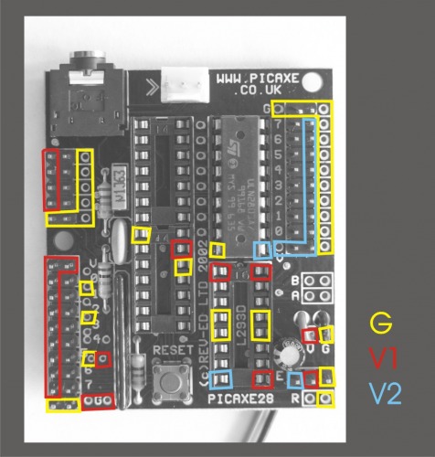
The standard setup of the board looks like this, all these areas are V:

So - what´s with the V1 / V2?
Well, everything returns to ground. But it can come from different sources. And they can have different voltage.
This way you can power a servo with V2, while the pulses that signals to the servo where it should turn to, is from the Microcontroller that runs on V1. All to the same G.
This 28 pin Project Board has 2 options:
Standard: See illustration above. V1 & V2 are connected, resoult: There is only one V. As you may have read from the documentation: It is the little jumper in the corner that connects V1 & V2, and when it is on, there is only V & G on the board.
2 power supplies: See illustration below. Take off the jumper, and connect a seperate power-supply to V2 (and that power supplie's G to ground, goes unsaid from now ;) - and the board will have V1 to the circuits and inputs, V2 to power external stuff, and G for all of it.
That way you can feed the chips with 5V, and the motors with 12V that would otherwise kill the chips.

So if you hook up a board with 2 power-supplies, this is where you have current and ground:
.. What is left?
Only the interesting stuff! :)
Power they need, the peripherals.. But it is the inputs and outputs that are interesting.
None of the above connections can be controlled by the Microcontroller, and unless you burn something, the Microcontroller does not sense weather you connect something to these or not.
This is where the input's and outputs come into the picture:

These conect to the Microcontrollers legs. Quite often, for advanced useage, things can be altered; An input can be switched in mode, so that it is an output etc. But you will figure that out, this is just the basics, as things are wired in default:
A: The digital inputs:
Connect a switch to V1 and one of these. In the program editor you can then write (let's say you have connected to leg 4, there are 8 in this area)
If pin4 = 1 then
...
B: The analouge inputs
How much corrent from V1 (or another source not more powerfull then V1) comes to this pin?
Well - it is not a question i ask, but what the pin asks :)
The answer is then returned into a variable, example, pin 2 out of the 4 in this area:
readadc 2, b1
Now the variable b1 is a value between 0-255, depending on how much corrent from V1 (or another source not more powerfull then V1) comes to this pin.
C: The IR-area
This is a quite undocumented feature on the board! It is used if you want to use standard TV-remote control-protocols to send to your microcontroller.
You can hook up IR ins-and out to anything, to measure IR, for instance to see if something is near or far, or white or black.. but you will have to do with analouge levels of signal and similar, you will not be able to transmit "signals" that can be translated to numbers such as TV romotes does. Most IR remote controls use 38 KHz sub-carrier, and this area let´s you hook up to that quite simply. You should only use it for that!
D: The Serial communication
The square on the picture should perhaps include the Jackstick :) This is the serial connection used to program and more.
You can also use output- and digital input pins for serial connection, but the ones on D are hard-wired
E: Direct outputs from the picaxe
These should (only) be used if you are trying to communicate "chip to chip". I think this is called TTL-level, where you let the chips talk to each other via pulses. This should not be used to drive anything, but it should allways be used if you want your chip to talk to others, like in this example:
https://www.robotshop.com/letsmakerobots/node/66
F: Output pins
These are what you should start with, IMHO: Connect a LED or something (Remember LED´s should turn the right way around) to one of these (other LED-leg to ground).. let´s say you connect to leg 3 out of the 8 in this area. Write:
high 3
to turn power on
low 3
to turn it off
Note that if you are using a motor controller, you should not use leg 4, 5, 6 and 7 for anything else!
These pins are also used for standard servo connection.
G: Motor connections A & B
The board is made for the typical applications, and one is where you want to control 2 motors, and being able to switch directions on them.
Of course if you only can turn things on or off, it can be hard to reverse a motor.
You can purchase a L293D motor controller - chip, and place it in here.
Then read the documentation for how to make output 4, 5, 6 and 7 control 2 way-drive of 2 motors connected to A & B outputs. (one motor to A and one to B, not 2 times A+B)
H: The reset switch
If you mount your board in a case or something, and would like to be able to remote-reset the Microcontroller, add a switch to this, press it and.. Hello? I remember nothing, let´s start all over!
Update: Elliot just wrote that you could use a better motor driver for the board. I have not had the chance to test it myself yet, but it sounds very interesting :)
Update II: psy has made a great documentation on the "Support Chips" that fits into the board.

 Some day I will.