

Lynxmotion Quadrino Nano - Raw Sensor Values


The Lynxmotion Quadrino Nano Flight Controller (with GPS) was originally designed as a flight controller for drones but, it also has awesome applications for robotic rovers too. Composed of an ATmega2560 (Arduino Mega Chipset), a collection of sensors, GPS and a host of I/O options it is an ideal "sensor ball" for navigation, positioning and more.
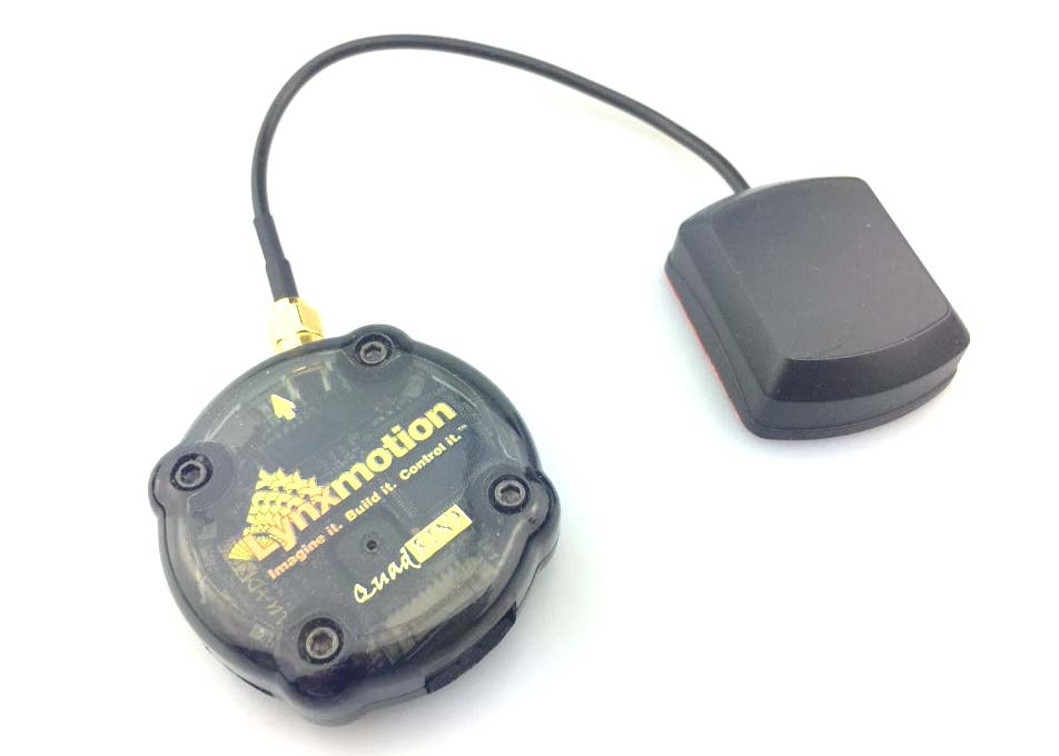 Lynxmotion Quadrino Nano
In this tutorial we'll be working with a small Arduino program that will give us data from:
- the MPU-9150 (gyroscope, accelerometer, magnetometer)
- the MS5611 (barometer)
- the Venus838FLP (GPS module)
Requirements
- Arduino IDE
- Lynxmotion Quadrino Nano Flight Controller (with GPS)
- The Quadrino-Nano-sensor files (github)
Helpful Experience
This tutorial is targeted at beginners, but some experience with the the Arduino IDE and C++ files (.cpp and .h) is helpful but, not required.Download and open the files
First, download the files. Second, navigate to the Arduino IDE and go to "Sketch/Include Library/Add .ZIP Library and select ZIP file you just downloaded. (if you need any help with this step see https://www.arduino.cc/en/guide/libraries#toc4). Arduino IDE - Library Install
Then navigate to your Arduino Examples folder. Towards the bottom of the list you will see an item called "QuadrinoNano_SensorDataLibrary", navigate there and click the "QuadrinoNano_SensorData" item.
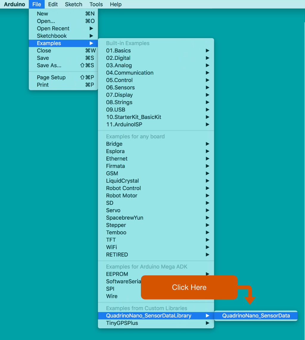 Arduino IDE - Quadrino Example
Upload files to the Quadrino Nano
Next we're going to upload the files to the Quadrino Nano and work with the code before we dive into the specifics.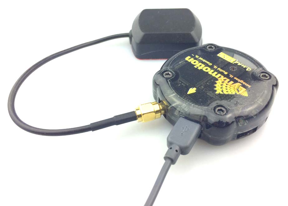 Lynxmotion Quadrino Nano - USB Connection
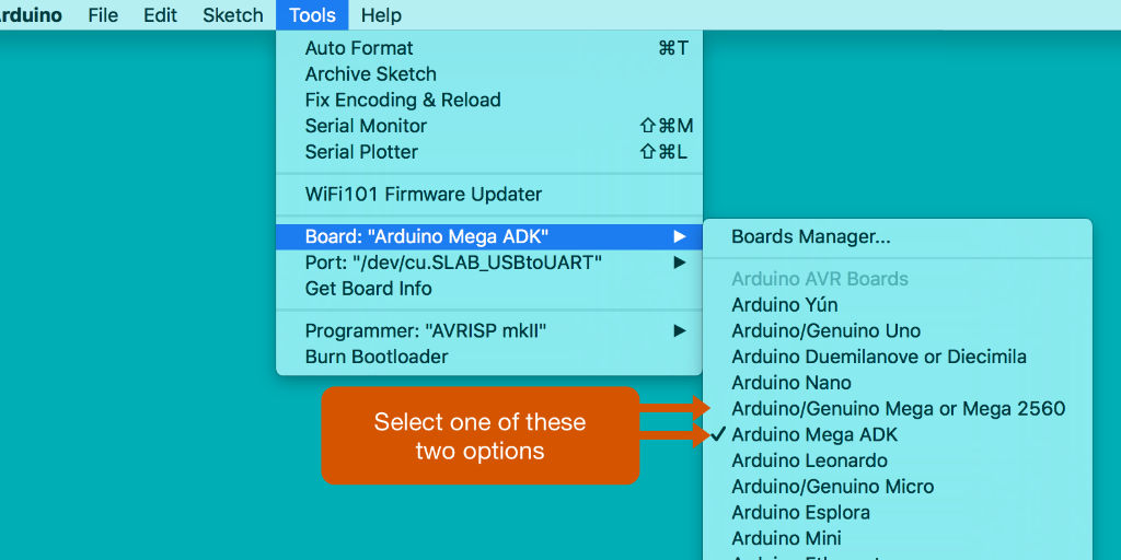 Arduino IDE - Board
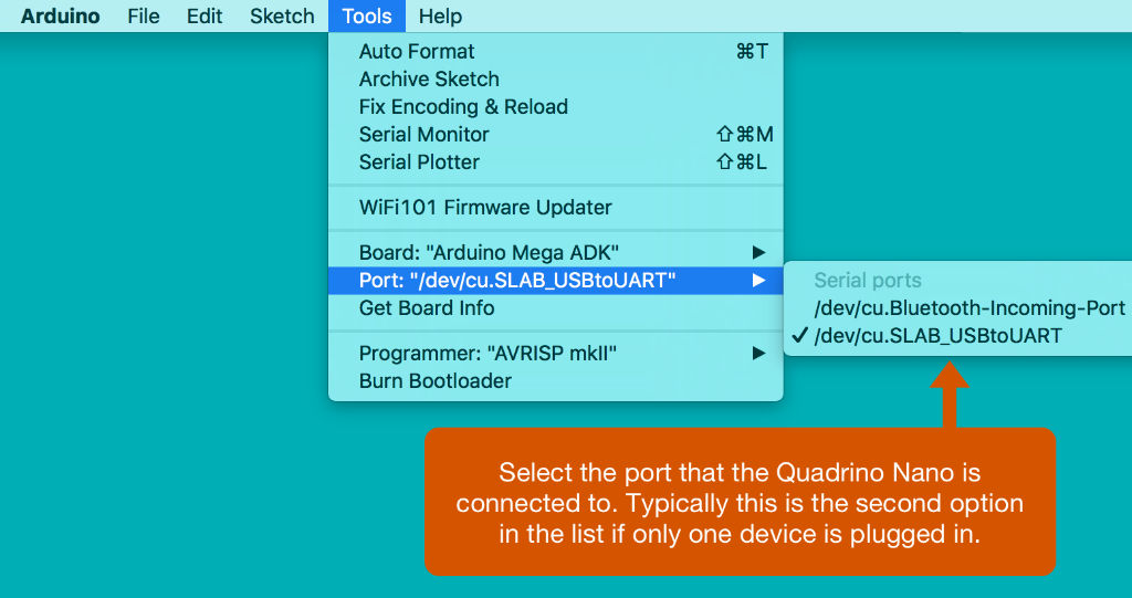 Arduino IDE - Port
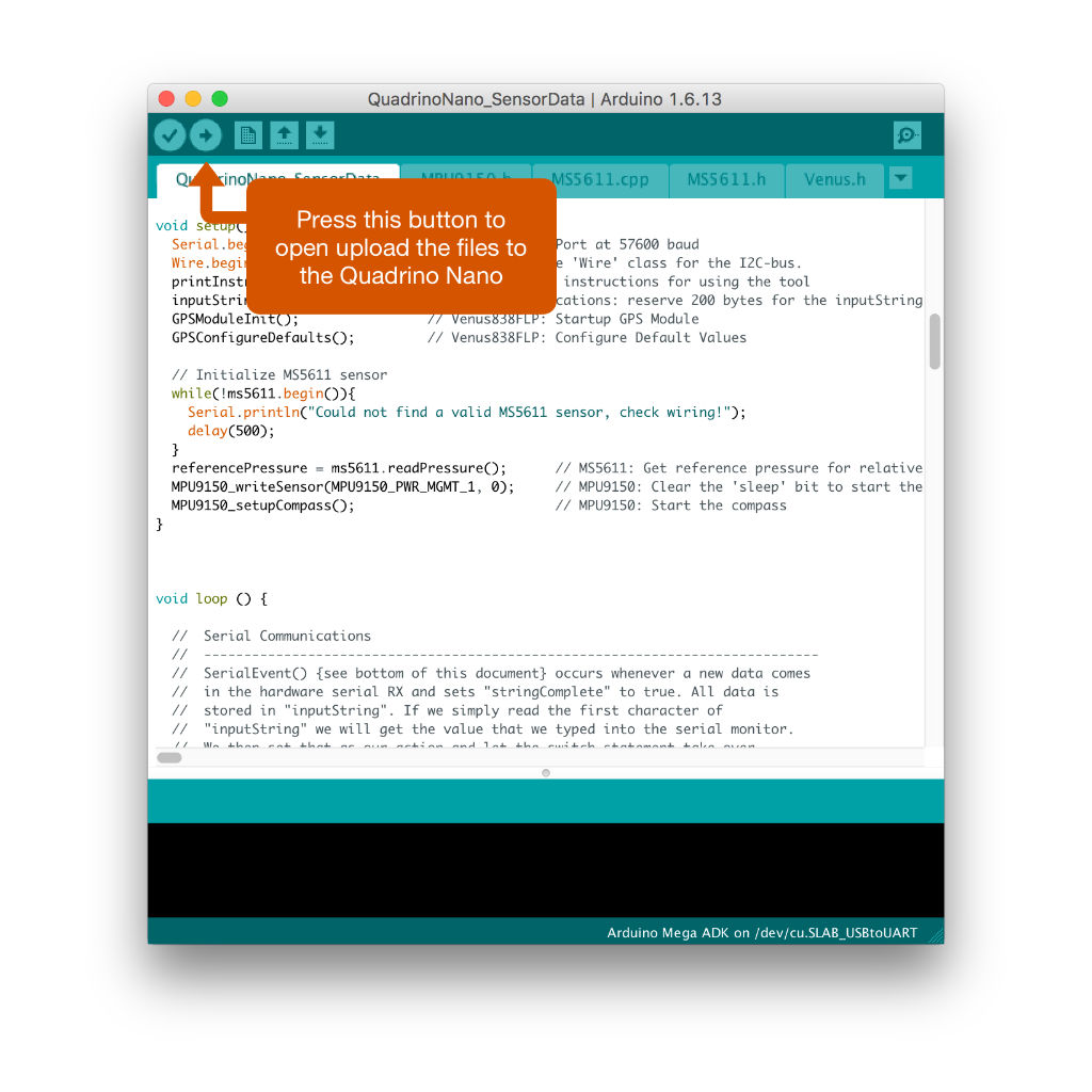 Arduino IDE - Upload
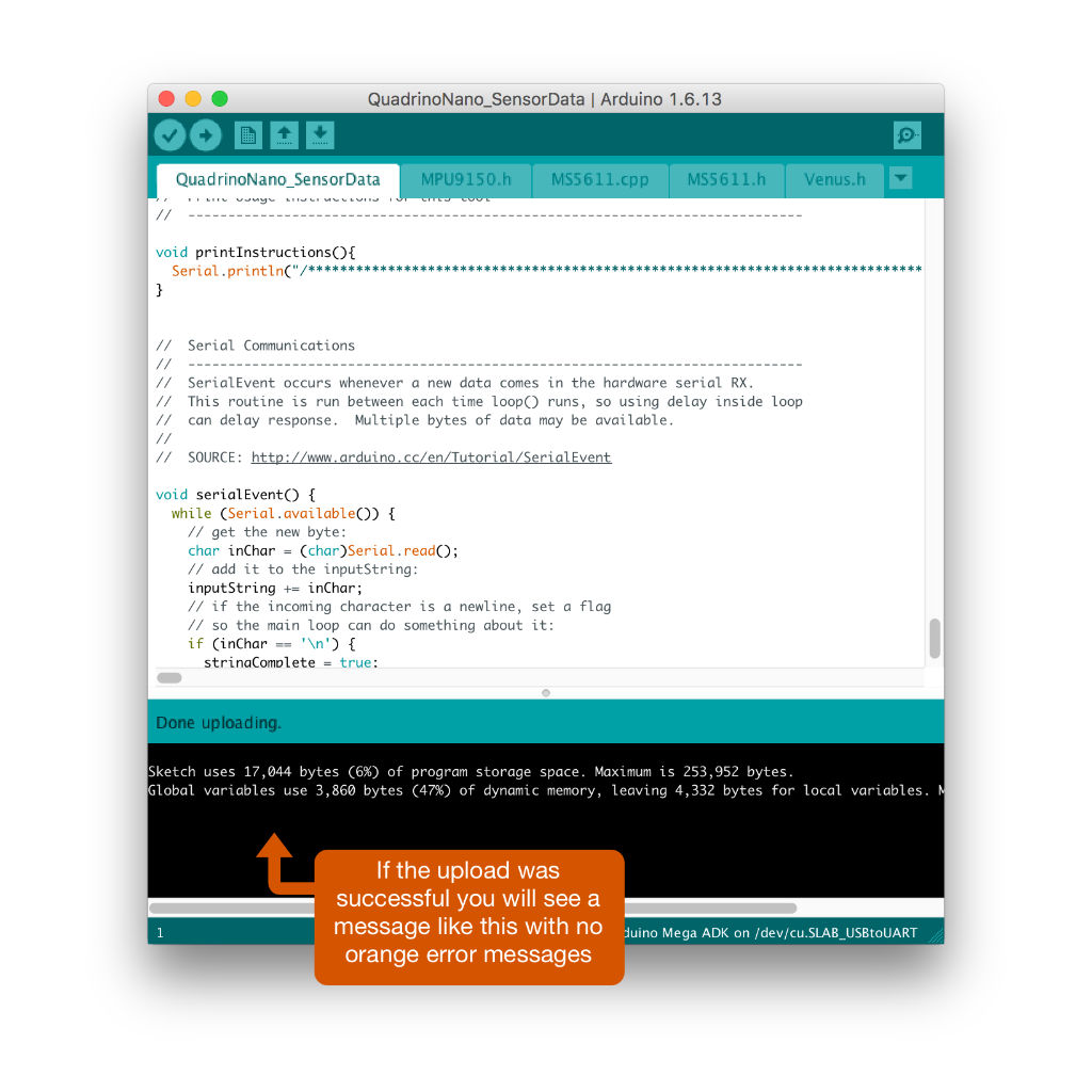 Arduino IDE - Uploaded
- Make sure the Quadrino Nano is plugged in (this happens to me all the time)
- Make sure the proper "Board" is selected from the tools menu
- Make sure the proper "Port" is selected from the tools menu
- Copy the error message and paste it in Google, often there will be a blog article or a Stack Overflow question about the issue
- Check the official Arduino site especially the troubleshooting section
Run some commands
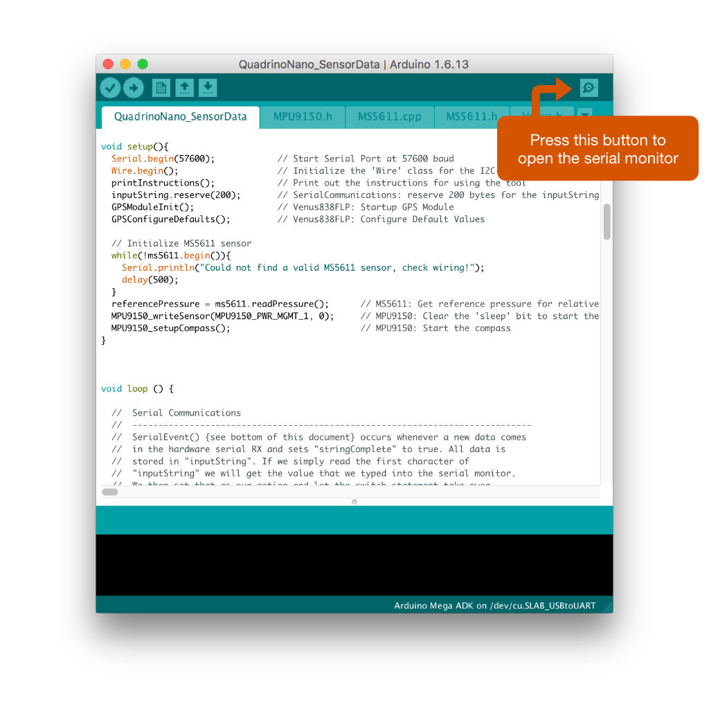 Arduino IDE - Serial Monitor
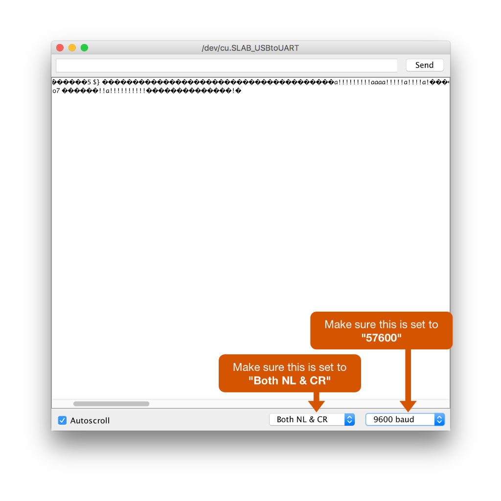 Arduino IDE - Serial Settings
 Arduino IDE - Serial Commands
Diving into the sensor commands
Probably the best way to get an understanding of how we read and interact with the Quadrino Nano's sensors is to take a look at the code itself. The function names are fairly self explanatory and the included notes by the original developers and myself attempt to make these files as readable as possible. That said, we will take a little time to look at the basics of each sensor below.MPU-9150 commands and function files
The MPU-9150 is an Accelerometer, Gyroscope and Compass in a single chip. From the manufacturers (InvenSense) website:The MPU-9150 is a System in Package (SiP) that combines two chips: the MPU-6050, which contains a 3-axis gyroscope, 3-axis accelerometer, and an onboard Digital Motion Processor™ (DMP™) capable of processing complex MotionFusion algorithms; and the AK8975, a 3-axis digital compass. The part's integrated 6-axis MotionFusion algorithms access all internal sensors to gather a full set of sensor data.We communicate with it via I2C using the Arduino Wire Library. We read data from the accelerometer, gyroscope and compass in the same way by using a predefined function and predefined register addresses (often doing a two byte read, once for the low byte and again for the high byte).
/* Example - Read the value of the compass X-axis and save the value to a floating point variable called "compass_x_axis_value"
 MPU9150_readSensor(low_byte,high_byte)
 MPU9150_CMPS_XOUT_L = Compass X-axis low byte
 MPU9150_CMPS_XOUT_H = Compass X-axis high byte */
 float compass_x_axis_value = MPU9150_readSensor(MPU9150_CMPS_XOUT_L,MPU9150_CMPS_XOUT_H);
// Clear the 'sleep' bit to start the sensor.
MPU9150_writeSensor(MPU9150_PWR_MGMT_1, 0);

// Start the compass
MPU9150_setupCompass();

// Read the Accelerometer
MPU9150_readSensor(MPU9150_ACCEL_XOUT_L,MPU9150_ACCEL_XOUT_H); // X-Axis
MPU9150_readSensor(MPU9150_ACCEL_YOUT_L,MPU9150_ACCEL_YOUT_H); // Y-Axis
MPU9150_readSensor(MPU9150_ACCEL_ZOUT_L,MPU9150_ACCEL_ZOUT_H); // Z-Axis

// Read the Gyroscope
MPU9150_readSensor(MPU9150_GYRO_XOUT_L,MPU9150_GYRO_XOUT_H); // X-Axis
MPU9150_readSensor(MPU9150_GYRO_YOUT_L,MPU9150_GYRO_YOUT_H); // Y-Axis
MPU9150_readSensor(MPU9150_GYRO_ZOUT_L,MPU9150_GYRO_ZOUT_H); // Z-Axis

// Read the Compass
MPU9150_readSensor(MPU9150_CMPS_XOUT_L,MPU9150_CMPS_XOUT_H); // X-Axis
MPU9150_readSensor(MPU9150_CMPS_YOUT_L,MPU9150_CMPS_YOUT_H); // Y-Axis
MPU9150_readSensor(MPU9150_CMPS_ZOUT_L,MPU9150_CMPS_ZOUT_H); // Z-Axis
With these commands and the "MPU9150.h" you can easily get accelerometer, gyroscope and compass data from the MPU09150. NOTE:The source of the "MPU9150.h" file is http://playground.arduino.cc/Main/MPU-9150. Additional details about the file are available there.
MS5611 commands and function files
The MS5611 chip gives us altitude, barometric pressure and temperature. Like the MPU-9150, we communicate with it via I2C. There are a few basic commands defined in MS5611.h and MS5611.cpp that we use to get the readings from the chip (everything else in these files deals with I2C communications). The function names do a good job of explaining what each of these functions does.uint32_t readRawTemperature(void); uint32_t readRawPressure(void); double readTemperature(bool compensation = false); int32_t readPressure(bool compensation = false); double getAltitude(double pressure, double seaLevelPressure = 101325);The MS5611 chip is very easy to use:
- Simply including the MS5611.h and MS5611.cpp files in your Arduino sketch
- Include Wire.h
- Start Wire in "
void setup()" - Execute one of the functions listed above, and that's it
Venus838FLP commands and function files
The Venus 838FLP GPS module was the most difficult to find a simple working library for. After some research, I decided to start with the MultiWii drone software and delete as much of the unnecessary functionality as I could to give us the leanest GPS library possible. There may be ways to further optimize the code, but I've tried to leave it robust and useful for as wide an array of applications as possible. The Venus communicates via Serial unlike our other two sensors which use I2C. In our sketch, we're doing three things to get data from the GPS module:- Include the Venus838FLP.h file in our sketch
- Start the module by executing "
GPSModuleInit()"and "GPSConfigureDefaults()"in our "void setup()" - Run "
VenusReadAndPrint(2000)"whenever we want a reading.
"VenusReadAndPrint(2000)" reads the data from the GPS module with a timeout of 2000ms. This is a function I created to display the data and is defined at the bottom of the Venus838FLP.h file. "VenusReadAndPrint()" calls a function "VenusDispatchMessage(int result)" (defined right above "VenusReadAndPrint()") that looks like this:
void VenusDispatchMessage(int result){
 //f.GPS_FIX = venus_ctx.location.fixmode >=2;
 Serial.print("Latitude: ");
 Serial.print(float(venus_ctx.location.latitude/10000000.000000),6); // With 1.9 now we have real 10e7 precision
 Serial.print("\t Longitude: ");
 Serial.print(float(venus_ctx.location.longitude/10000000.000000),6);
 Serial.print("\t Altitude: ");
 Serial.print(float(venus_ctx.location.sealevel_alt /100));
 Serial.print("m \t Satelite Count: ");
 Serial.println(venus_ctx.location.sv_count);
 //GPS_coord[LON] = venus_ctx.location.longitude;
 //GPS_altitude = venus_ctx.location.sealevel_alt /100; // altitude in meter
 //GPS_numSat = venus_ctx.location.sv_count;

 // note: the following vars are currently not used in nav code -- avoid retrieving it to save time
 // also, Venus8 doesnt provide these in a way that we can easily calculate without taking cpu cycles
 //GPS_speed = venus_ctx.location.ground_speed; // in m/s * 100 == in cm/s
 //GPS_ground_course = venus_ctx.location.ground_course/100; //in degrees
}
This function contains all the variables and values you would need to create almost any application that uses GPS. Feel free to modify "VenusReadAndPrint" and "VenusDispatchMessage" to create your own functions that store the GPS data to global variables or return values for setting local variables and more.
NOTE: The MultiWii source is availble here: https://github.com/multiwii/multiwii-firmware.
Conclusion
As we can see, the Lynxmotion Quadrino Nano Flight Controller (with GPS) is an ideal "sensor ball" for all kinds of sensor intensive projects. The sample code has a fairly small footprint (6% of memory and 47% of dynamic memory) and could easily be optimized further by removing variables and trimming the libraries/sensor functions to include only the exact code your specific application needs (we included the seemingly redundant functions in order to facilitate the greatest range of applications that readers of this tutorial may wish to create). Happy making!Continued reading
- Library/Sensor Function Sources
- MultiWii Source https://github.com/multiwii/multiwii-firmware
- MS5611 Source https://github.com/jarzebski/Arduino-MS5611
- MPU9510 Source http://playground.arduino.cc/Main/MPU-9150
- Quadrino Nano Useful Links (RobotShop)
- Quadrino Nano Useful Links (Lynxmotion)
Thanks for helping to keep our community civil!
Notify staff privately
You flagged this as spam. Undo flag.Flag Post
It's Spam
This post is an advertisement, or vandalism. It is not useful or relevant to the current topic.
Report Reason
This post is an advertisement, or vandalism. It is not useful or relevant to the current topic.
You flagged this as spam. Undo flag.Flag Post
✅ Your Post Has Been Submitted Successfully!
Your post is currently under review by our moderation team. The review process usually takes up to 48 business hours.
You can track your post's status in the "My Content" section of your profile. Once approved, it will be published and visible to others.

Thank you for contributing to our community!