

Lynxmotion Quadrino Nano - Battery Monitoring & Alarms


MultiWii Setup
There are several ways to set up MultiWii values via software, but for simplicity we suggest using the Quadrino FCT (Firmware Configuration Tool) as it will load the correct values for a 3s LiPo to the Quadrino Nano. The Quadrino FCT uses the MultiWii software at its core, but presents the user with a much more intuitive interface. The values which are loaded to the flight controller can later on be changed in the WinGUI application without the need to flash the board via the FCT.
1 - FCT OptionsOpen the FCT application and go to the "Battery" tab which is located in the "Options" page. |
 FCT - Options Page FCT - Options Page |
2 - Enable Battery Voltage MonitoringOn the same page, check "Enable Battery Voltage Monitoring". You do not need to make the physical connections yet. |
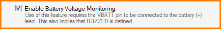 FCT - Battery Monitoring FCT - Battery Monitoring |
3 - Set valuesThe default settings are for a 3s (11.1V) LiPo battery, but you can change the alarms set-points (number 107 will stand for 10.7V). |
 FCT - Alarms Levels FCT - Alarms Levels |
4 - Activate BuzzerIn the "Misc" tab, make sure the "Buzzer" is enabled (which should automatically be enabled when "Battery Monitor" is set) |
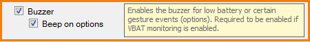 FCT - Buzzer Options FCT - Buzzer Options |
5 - Flash the Quadrino NanoGo to the "Flash" page and flash the Quadrino Nano with the newly added options. Ensure your Quadrino Nano is connected to the computer via USB cable. |
 FCT - Flash Firmware FCT - Flash Firmware |
6 - WinGUI Connect & LoadConnect to the WinGUI application and hit "Load Defaults" in the top bar |
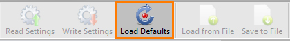 WinGUI - Load Default Values WinGUI - Load Default Values |
6 - WinGUI Write SettingsWith the values loaded, click "Write Settings" to get those settings written in the Quadrino Nano memory |
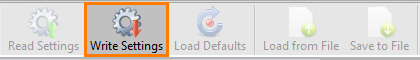 WinGUI - Write Settings WinGUI - Write Settings |
Quadrino Nano Wiring
There are two pins associated with the battery monitoring and buzzer functions which are standard on all MultiWii based controllers. These pins can be used simultaneously depending on the setup needed but if no external buzzer is set up, only the LED labeled "LiPo Alarm" will blink when the battery is low. Connect your LiPo battery and buzzer as in the drawing below using the Lynxmotion Quadrino Nano IO wiring harness.
- VBATT (pin 19) is the battery sensing pin on the Quadrino Nano and where you need to connect the positive terminal of your battery's charging connector. Usually there is a resistor which needs to be added between the controller pin and the battery's positive terminal, but we already took care of this on the Quadrino Nano PCB so you can connect a 3s LiPo battery directly.
- BUZZER (pin 20) activates the buzzer when this pin is triggered to Ground via the MultiWii software. An Arduino-based controller used with MultiWii is able to pass more current by grounding a pin than being powered from it, which is why we use the pin as the ground in this application.
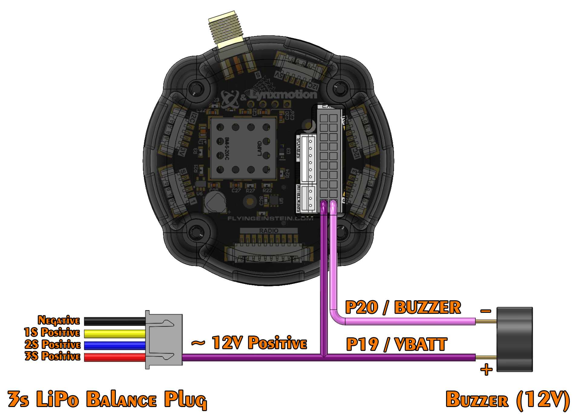 Lynxmotion Quadrino Nano - VBATT & BUZZER Connection
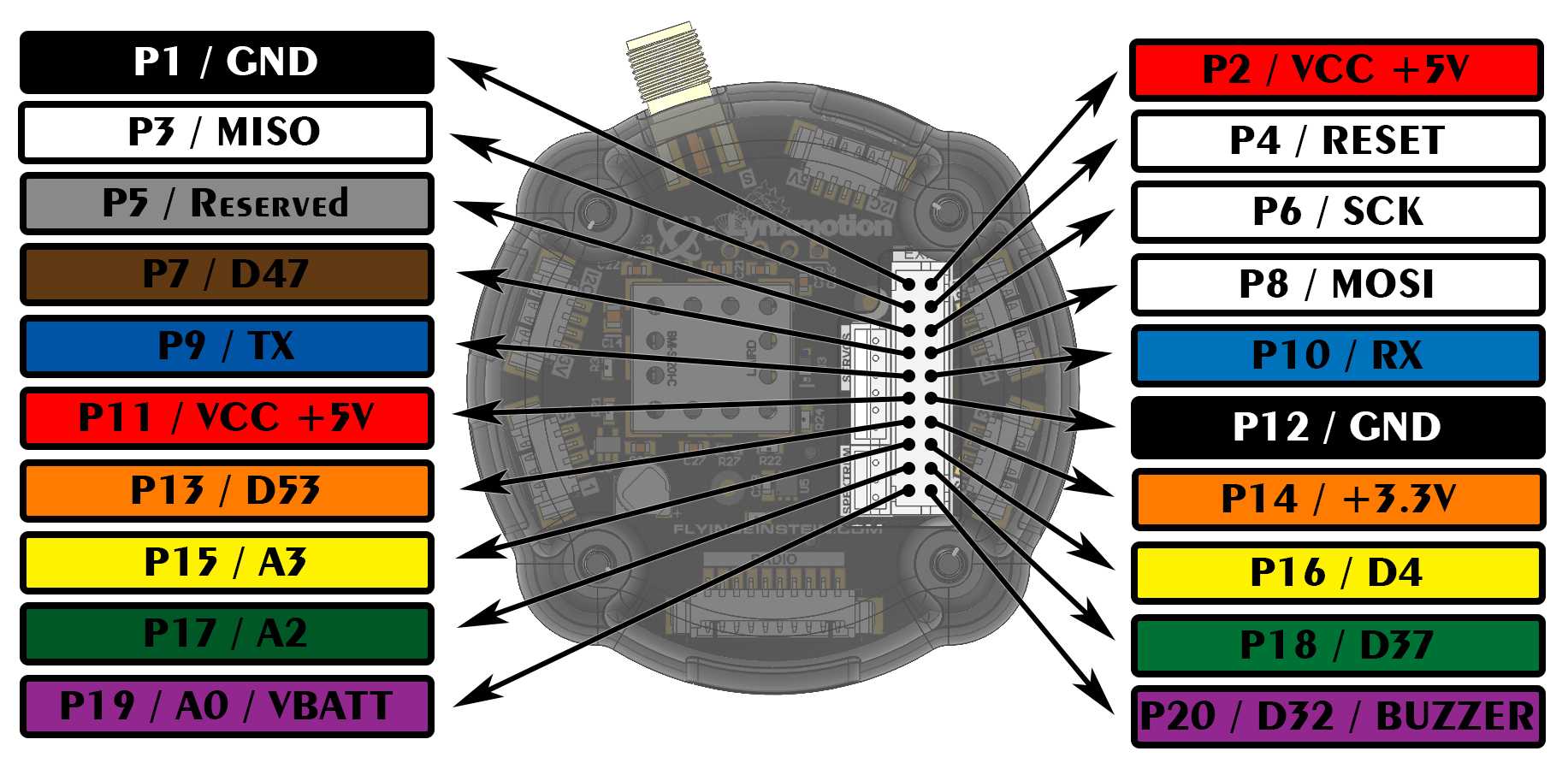 Lynxmotion Quadrino Nano - I/O port Color Code
Additional Information:
1 - Enable Battery Voltage MonitoringCheckbox used to Enable the battery monitoring feature2 - WARNING LEVELFirst warning level; it will trigger the buzzer / LED once every 3 seconds.3 - DANGEROUSSecond warning level; the battery is almost empty and the buzzer / LED is triggered in two short bursts every 3 seconds.4 - CRITICALFinal warning; this will cause the buzzer / LED to stay on constantly.5 - VBATT SCALEThis is used to scale the VBATT input to match the battery's real voltage. The default value for a 3S battery would be 128 but changes can be applied if needed. Here is a simple equation to correct the scaling: New VBAT SCALE = ( GUI Vbat Scale * GUI Voltage ) / Measured Voltage |
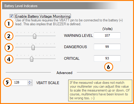 FCT - Battery Level Indicators FCT - Battery Level Indicators |
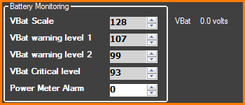 WinGUI - Battery Monitoring Options
Thanks for helping to keep our community civil!
This post is an advertisement, or vandalism. It is not useful or relevant to the current topic.
You flagged this as spam. Undo flag.Flag Post
Your post is currently under review by our moderation team. The review process usually takes up to 48 business hours.
You can track your post's status in the "My Content" section of your profile. Once approved, it will be published and visible to others.

Thank you for contributing to our community!