This repair guide explains how to replace the light-touch bumper array on a
500 series Roomba. For details on how to first disassemble your Roomba, please see
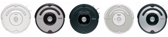
Roomba 500 Series Servicing and Repair Guide Chapter 3: How to Open Up Roomba. Some of the 500 series Roombas are pictured below:
 12 How to Replace Roomba’s Light-Touch Bumper Array
12.1 How to Remove the Old Light-Touch Bumper Array
Roomba replacement bumper sensor array
12 How to Replace Roomba’s Light-Touch Bumper Array
12.1 How to Remove the Old Light-Touch Bumper Array
Roomba replacement bumper sensor array can be found at RobotShop.
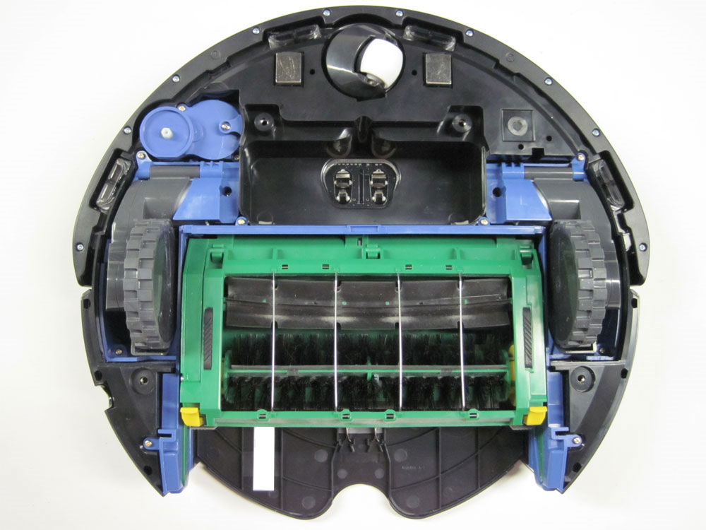
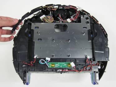
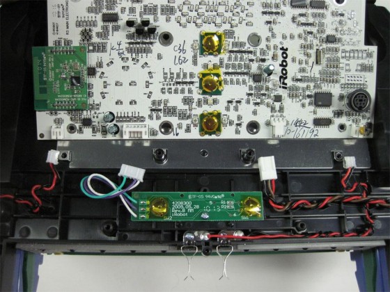
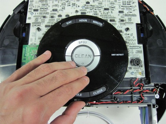
12.1.1 Start with the frame disassembled so you have access to the control panel.
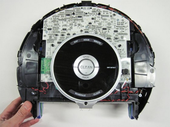
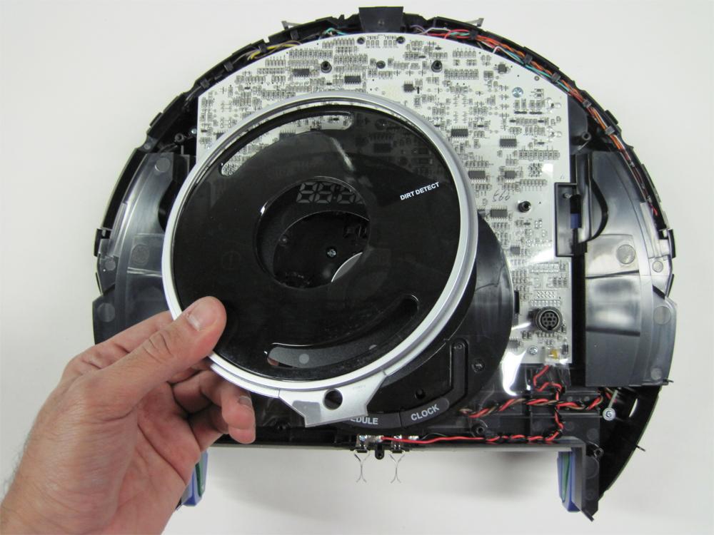
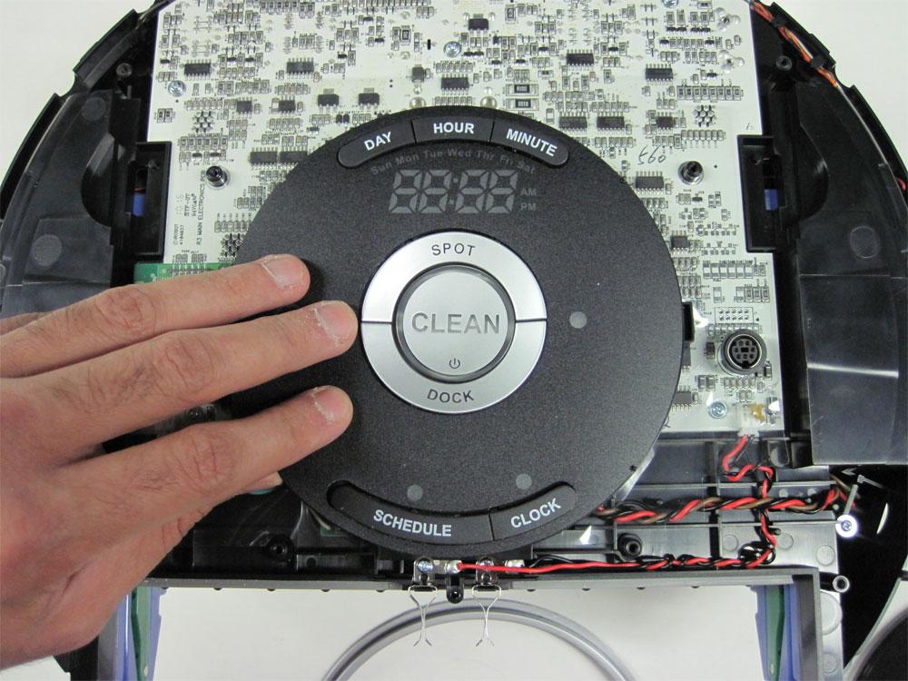
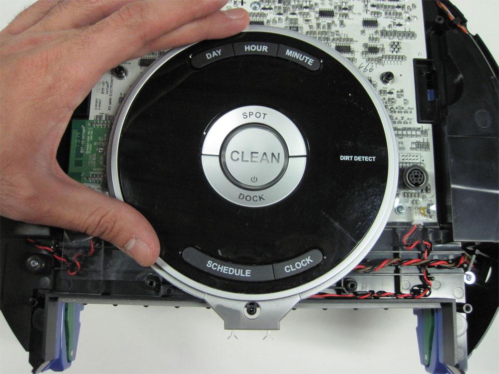
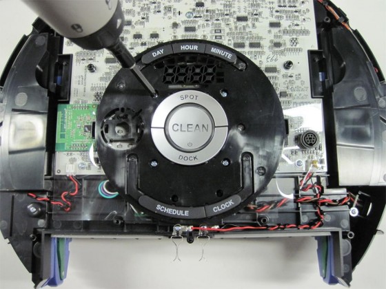
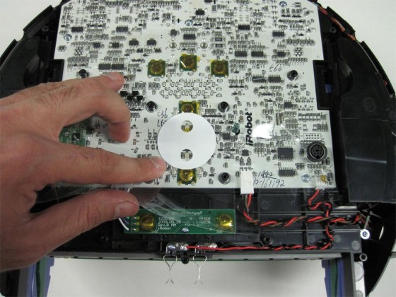
12.1.2 Remove the display bezel set.
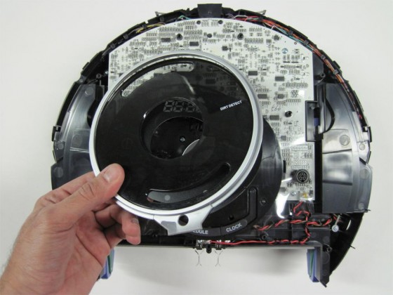
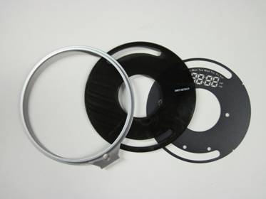
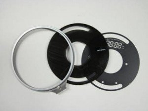
12.1.3 Notice that the display bezel set has three parts that sit one on top of the other, as shown in the picture.
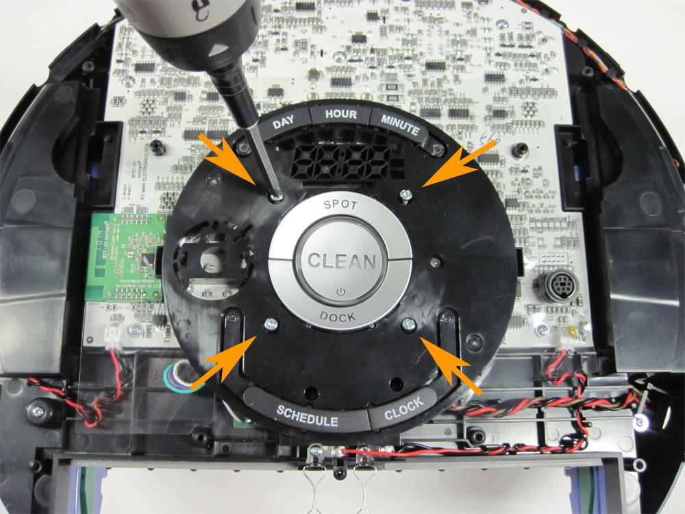
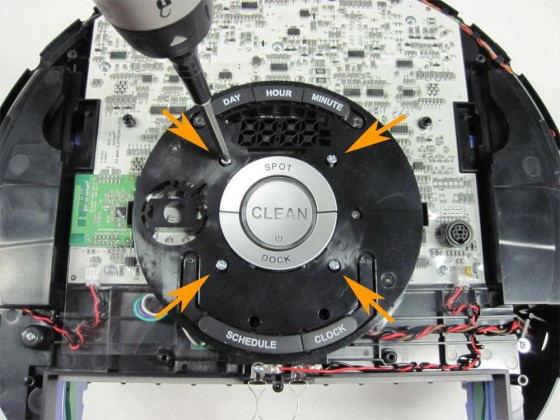
12.1.4 Loosen the four screws holding the control panel in place.
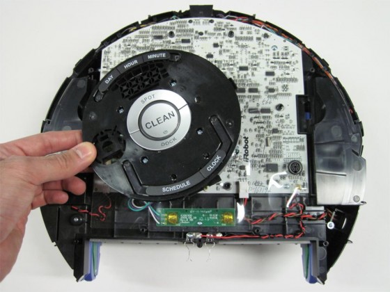
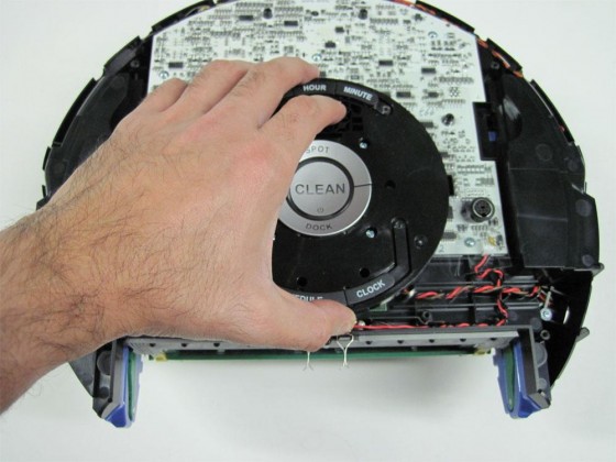
12.1.5 Remove the control panel from the Roomba.
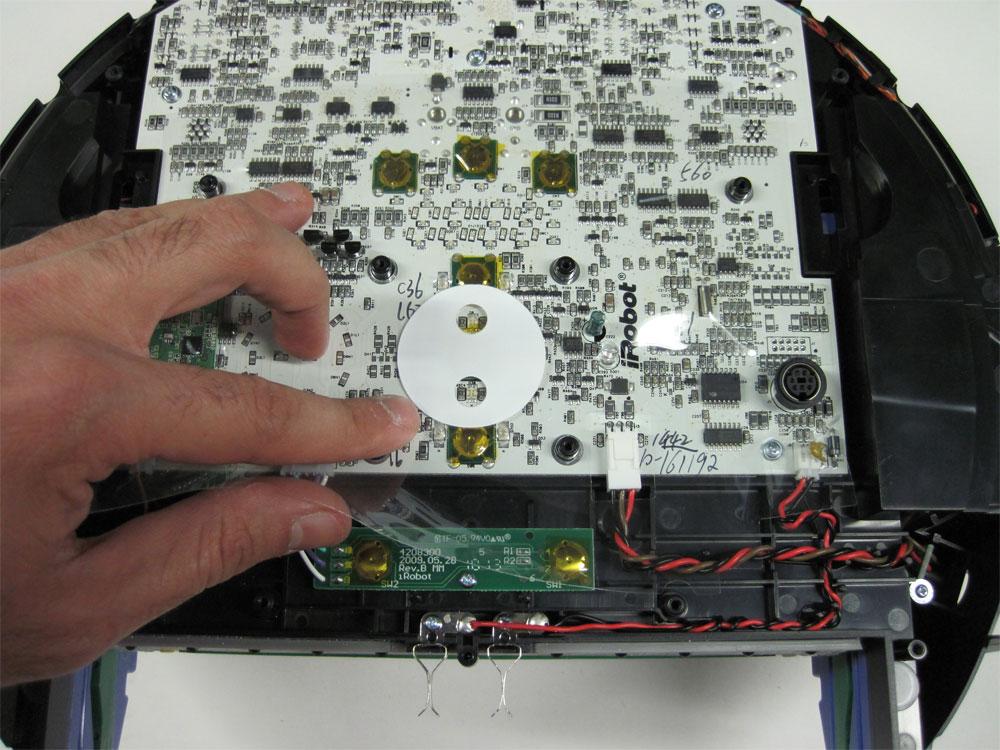
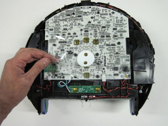
12.1.6 Remove the transparent plastic insulator layer from on top of the Roomba’s motherboard.
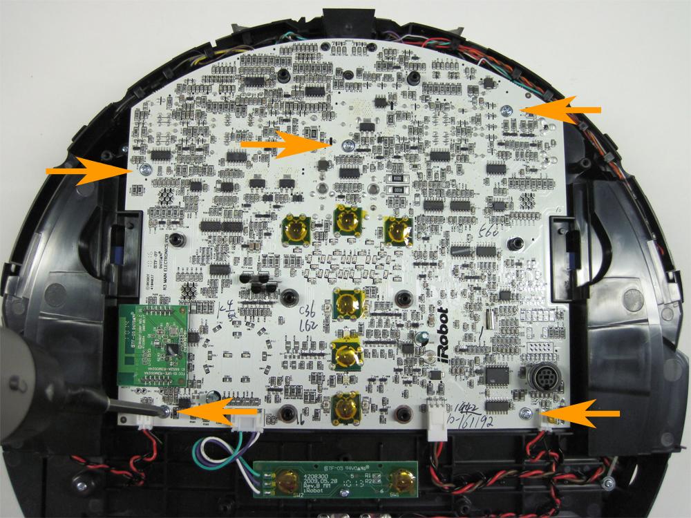
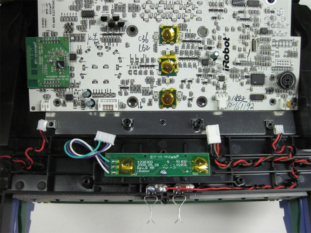
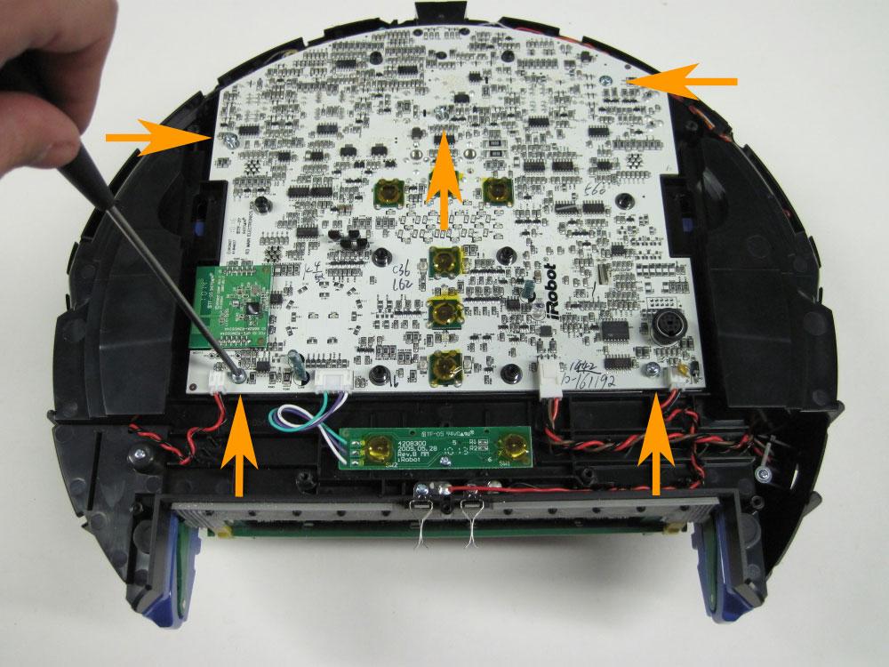
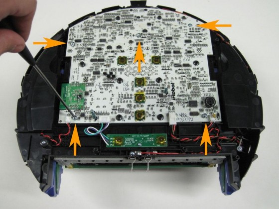
12.1.7 Loosen the five screws holding the motherboard to the Roomba.
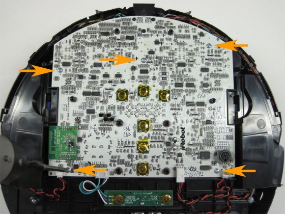
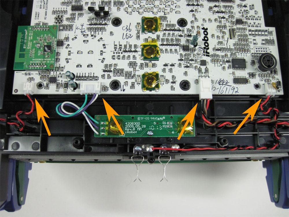
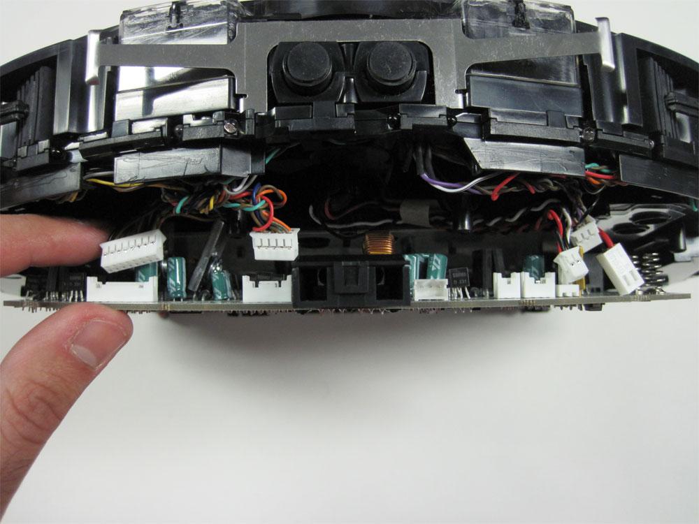
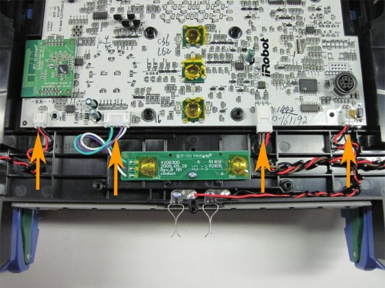
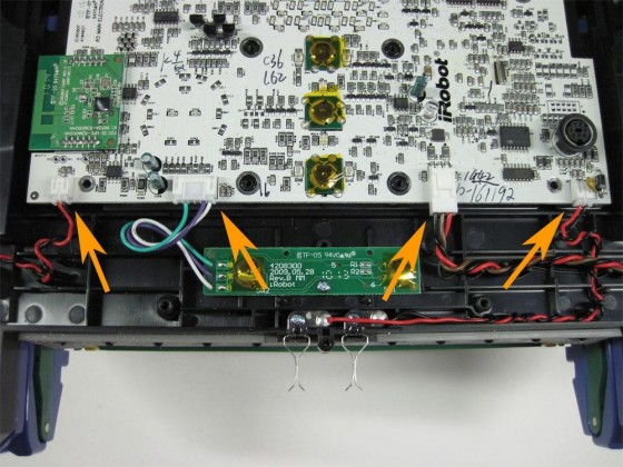
12.1.8 Next, unplug the four connectors at the bottom of the motherboard, shown by the arrows at right.
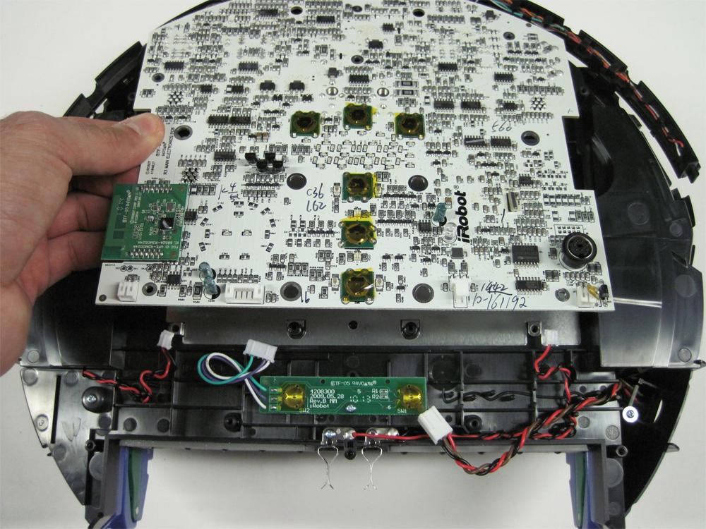
12.1.9 Once the connectors are unplugged, lift the motherboard up from the bottom to loosen it. It will not come out of the Roomba yet, as the top portion must also be disconnected.

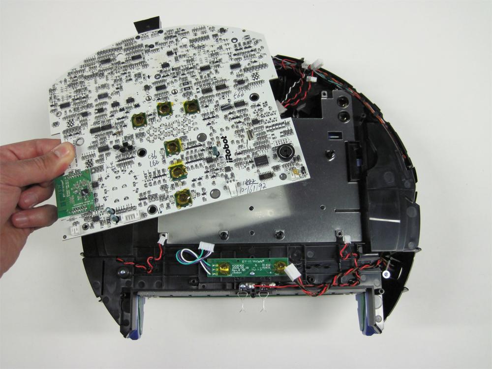
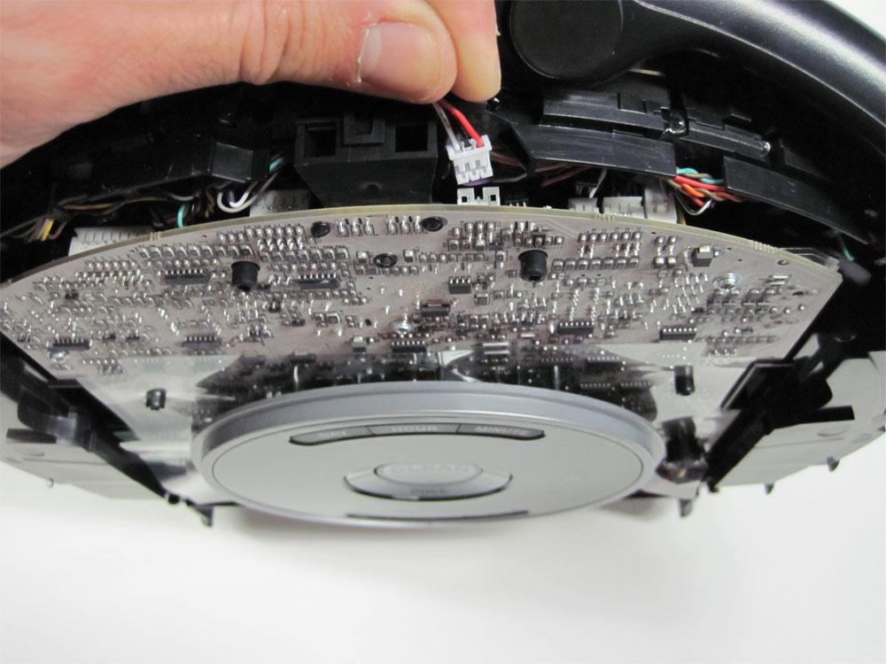
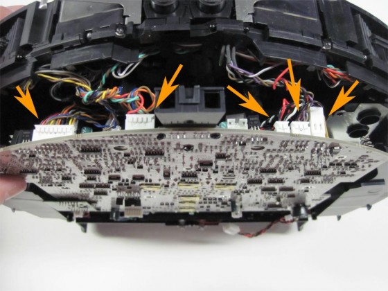
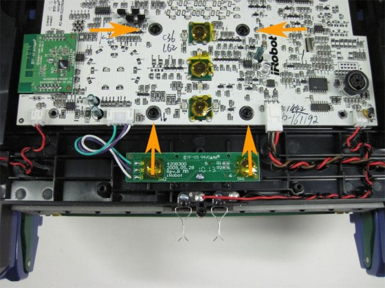
12.1.10 Lift the front end of the motherboard up slightly and disconnect all five connectors from the motherboard.
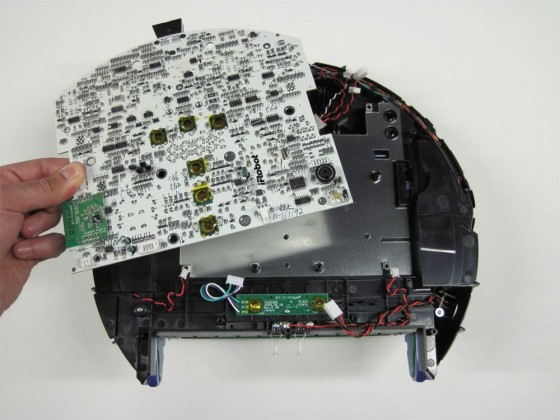
12.1.11 Now remove the motherboard from the Roomba.
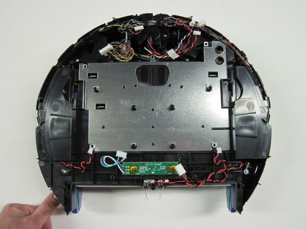
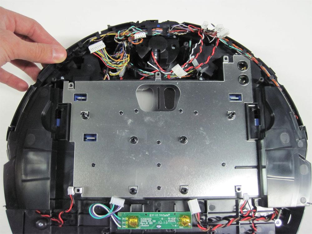
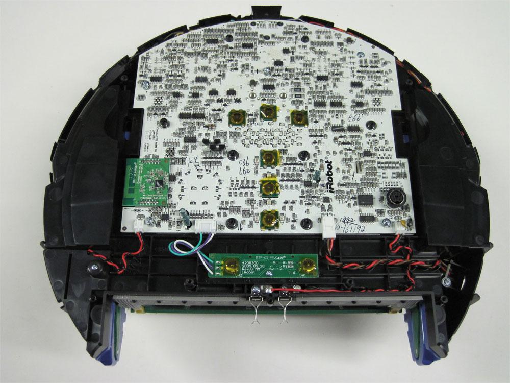
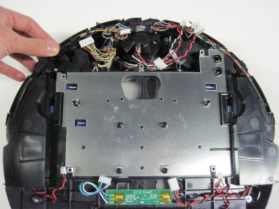
12.1.12 View or Roomba with the motherboard removed.
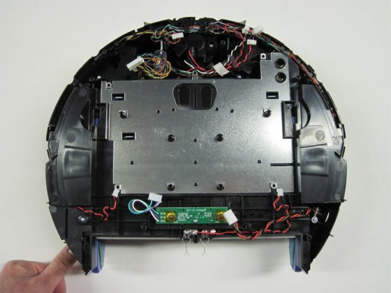
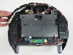
12.1.13 Lift up the light-touch bumper array from either side of the Roomba, as shown in the picture.
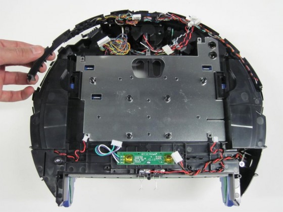
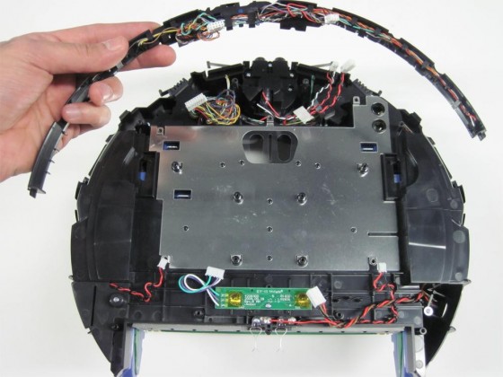
12.1.14 Continue lifting to remove the light-touch bumper array from the Roomba.
12.2 How to Install the New Light-Touch Bumper Array
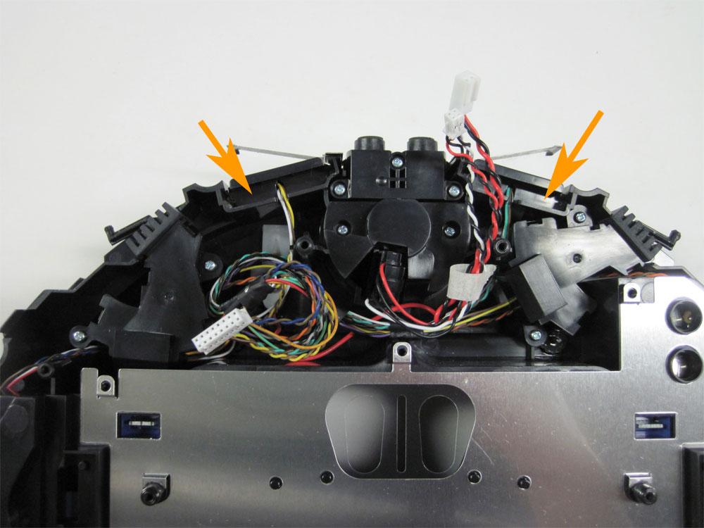
12.2.1 View of Roomba with light-touch bumper removed. Notice the ‘holders’ for the two middle cliff sensors. This will be important for the next step.

12.2.2 The new light-touch bumper array has two tabs as shown by the arrows. When installing it, these must match up and fit
behind the two cliff sensors shown in the previous picture.
12.2.3 Lining up the tabs on the light-touch bumper array with the cliff sensors holders, install the light-touch bumper array.
12.2.4 Reinstall the motherboard, starting at the bottom. Line up the motherboard with the four bottom connections.
12.2.5 Reconnect the four connectors, as shown by the orange arrows.
12.2.6 Line up the board so that the four holes pictured are aligned with the four corresponding posts on the Roomba’s frame underneath. This will help you with the next step.
12.2.7 Stand the Roomba on end to make connecting the top of the motherboard easier.
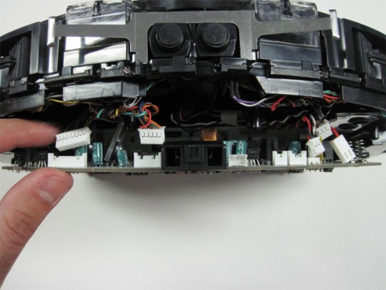
12.2.8 Reconnect the five connections shown by the orange arrows. The connections can only go in one place each.

12.2.9 With all the connectors properly connected, push the motherboard down into place.

12.2.10 Place the five motherboard screws in place and tighten them down. Do not use an electric screwdriver as these threads are plastic and particularly delicate.
12.2.11 Place the transparent plastic insulator back over the motherboard.
12.2.12 Place the control panel in on the motherboard, careful to line up the four screws with the four threaded posts underneath.
12.2.13 Tighten the control panel’s four screws in place.
12.2.14 Place the first layer of the control panel display as shown in the picture.

12.2.15 Put back the control panel display cover, making sure the orientation is correct.
12.2.16 Place the control panel display trim around the cover, making sure the screw hole is at the bottom.

12.2.17 You now have successfully replaced your Roomba’s light-touch bumper array.

For details on how to reassemble the Roomba’s frame, please see the
Roomba 500 Series Servicing and Repair Guide Chapter 3: How to Open Up Roomba.
Roomba replacement parts can be found at RobotShop.


 12 How to Replace Roomba’s Light-Touch Bumper Array
12.1 How to Remove the Old Light-Touch Bumper Array
Roomba replacement bumper sensor array can be found at RobotShop.
12.1.1 Start with the frame disassembled so you have access to the control panel.
12 How to Replace Roomba’s Light-Touch Bumper Array
12.1 How to Remove the Old Light-Touch Bumper Array
Roomba replacement bumper sensor array can be found at RobotShop.
12.1.1 Start with the frame disassembled so you have access to the control panel.