

My iteration at building the famous MouseBot, originally (Mousey, the Junkbot?) created by Randy Sargent.
I present to you YUMBBBBMH (Yet Un-named Mouse Bot Being Built By My Hands) previously known as MouseBot Still To Be Named and now A.K.A GhostRoachMouseBullRam CrazyBot.
(...or perhaps just GRMBR CB for short? :P)
February, 12th 2012
As per popular request I hereby also add (as an attachment) the proper pronunciation soundfile of this bot's true name (c'mon this was is way easy).
October, 11th 2012
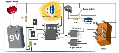
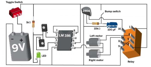
So after the tip from birdmun regarding what was on the LM386 datasheet application notes regarding gain, I decided to do some tests with capacitors. At first, seemingly I had not much success, but then again my 9V batteries were low on juice and I got lazy and did not recharged them at the time. Last night finally I've put on charging over night, and today decided to fiddle with the mouse bot again. After, making certain everything was connected, the mouse bot lost it's previously typical crazy spin... and instead turned into a crazy shooting arrow. Problem: It crashed so hard against stuff that pop goes the tiny whiskers. So after some brainstorming with ossipee I went looking for a wire cloth hanger... and a couple of pliers and a few (considerable) twists later I got myself a couple of cross sturdy whiskers and mounted them on some holes on the microswitchers (after so filling so they would fit). For enhanced (animal) security at the end of each whisker I've deposited a blob/ball of hot glue. Turn it on, and success, now it zooms around like an enraged brutish mouse, without the whiskers falling off. I now consider this project, my second robot project, first to be fully completed. So, the MAJOR trick is to connect pins 1 and 8 of the LM386 through a CAPACITOR and not directly (see altered schematic bellow), otherwise you might end up with a [clockwise|counterclockwise] crazy spinner.
September 9th, 2012
So, I've tracked the uneven voltage problem, basically pin 1 and 8 on the LM386 were tied together to provide maximum gain, by cutting that connection I was able to leverage the voltages, however I've lost noticeable gain. Solution (EDIT: or so I thought): Connect pins 1 and 8 through a resistor. My experiments told me that I needed high (>1 kohms) resistor values to even out the voltage differences, however whenever I increase the resistance I also decreased the sensitivity hence this is going to take some fine tuning later on.
So the schematic should be something like (WRONG...):
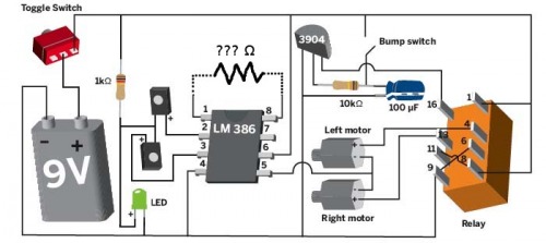
the value of the resistor (range of potentiometer) will depend on the LEDs used for optical sensors. I found that normal LEDs and LDRs were unsuited for the task, the best results I got were with IR LEDs.
August 26th, 2012
Since my mousebot CCCW (crazy-counter clockwise) spinner I decided to dig it up again and run a bit more of diagnostics.
I've already measured that the voltages where un-evenly divided between both motors (even when the led "eyes" were blinded -- made a couple of little black hoods for them).
So, I've decided for a "clean" read. Opened the bot up, disconnected the motors and connected the mainboard with the battery. With the switch turned ON I read:
RIGHT motor vcc PIN: ~5V
LEFT motor vcc PIN: (-)3.4V
Turning the trimpot either way changes this readout very little. Previous measures directly done on the motor leads while running also shown me that adjusting the trimpot would either raise or lower the voltages but on BOTH motors at the SAME time.
So my guess, is that I inserted the trimpot in the wrong (INDEED WRONG, IGNORE BELLOW) place/way, but I have no idea why or how to fix it. See schema below.
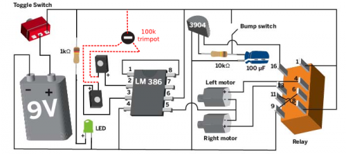
P.S. - See original (from the internet) schema near the end of this post.
July 21th, 2012
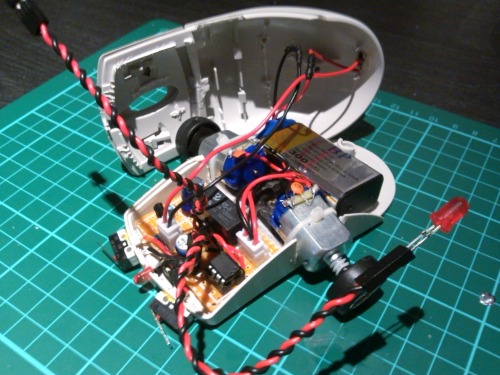
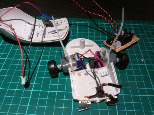
It's a few minutes past midnight and finally the still un-named mouse bot made it's first run. Actually it didn't went anywhere given that a wheel popped of after a second or two. And there's low traction. I'm now going to work on securing the wheels better to the motor pinions. Below you can see the final stages of the assembly!
July 20th, 2012
------------------------
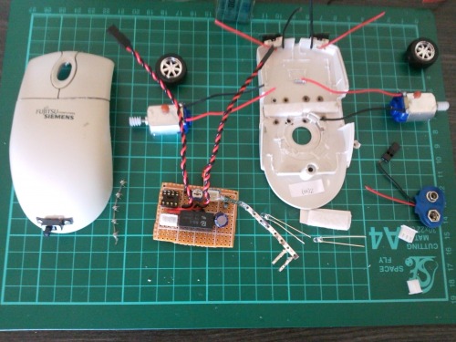
After a busy "night-ful" I got most of the base work done:
- Mouse entrails completely removed and made way for new "guts"
-- base (side holes for motors, padding for motors, front holes and mounting of bumper switches)
-- top (on/off switch mounted)
- Perf-board soldered all the components on a small stretch of perf-board
TODO:
- Apply proper connectors to dangling leads;
- Connect everything and test; if(notWorkingProperly){curse(HIGH);}
- Mount/attach the motors and respective wheels
- Close everything up, cross fingers & hope for the best
July 19th, 2012
----------------------
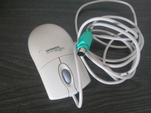
Got a suitable candidate PS/2 mouse to use as a carcass.
July 18th, 2012
----------------------
Breadboarded it successfully according to the schematic as show at MAKE magazine of the first mouse bot just added another bump switch and a 100k trimpot:
[Colorful] Schematic:
Breadboard look (before trimpot):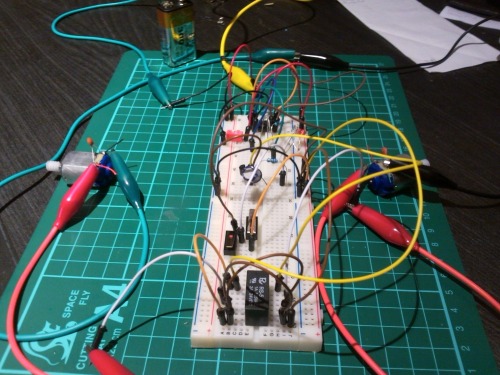
Zooms around searching for light
- Actuators / output devices: 2 small DC motors
- Power source: 9v battery
- Sensors / input devices: infrared led emitters
- Target environment: indoors
This is a companion discussion topic for the original entry at https://community.robotshop.com/robots/show/yumbbbbmh-a-k-a-ghostroachmousebullram-crazybot


