WiiDAR - or ($40 LIDAR)

double.png


First RADAR then LIDAR now WiiDAR !

WiiDAR is Light Detection And Ranging using a Wii Remote.

LIDAR units although great sensors tend to be expensive. The Hokuyo URG-04LX-UG01 is $1,175.00 USD.

Wii Remote has an infrared camera on the front of it.  The hardware can track up to 4 infrared spots at one time.  The information regarding these spots can be sent via bluetooth to another bluetooth receiver.  It turns out that the IR camera can also pick up the reflected light of a key chain laser if a filter is removed from the front of the WiiMote.  

In the following post I'll describe how to make a rough form of LIDAR using not much more than $40 worth of supplies.

Parts

  • WiiRemote - $38
  • 5 mW 650 nm Key Chain Laser - $2.79 - It's quite possible that an IR laser would have much better range - DVDs have IR laser diodes, but it would require focusing to an appropriate range.  Most laser IR laser pens are expensive and more hazardous since people can not actually see the beam.
  • Computer (if you reading this I assume you have one)
  • Blue Tooth Dongle $2 to $40.  This seems to vary wildly in price.  I got mine (RF-FLBTAD) for $30 at Best Buy.  I'm not including it in the price of the WiiDAR since it will not be damaged or modded in any way, and can be used for other things like headphones.
  • Servo - I used a servo, other configurations are possible. For example, motor and encoder, or stepper motor.
  • A Bunch O' Software - I used MyRobotLab wiiuse and wiiuseJ - all free, yet will require work (I said "free" not "easy")


Step 1

Glue  pen laser and wii to the top of the servo.  I mounted my laser at about 4" away and with a 65 degree tilt towards the wii camera.  The 65 degrees is almost arbitrary.  I was interested in ranges of about 2 to ~40 inches.  With that angle the horizontal disparity of the laser point is at a maximum within the range of ~40".  This would be the preferred mounting orientation, but the center of gravity would adversely affect the servo.  I had to mount the camera further forward.  Soon, I will be desoldering the camera, and mounting it on the axis of the servo.

preferred mounting

wiidar_pref.png.jpg

actual

Step 2
Remove the WiiMote IR filter with these instructions.  At this point, you just need to take the IR filter out.

Step 3
Mount the WiiMote and Laser/Servo to a surface where you can start to do some tests.  A little hot glue might be in order.  Calibrate using a tape measure and some trig.

Step 4
Download MyRobotLab and unzip it.
Download thirdParty.zip and unzip the contents into the myrobotlab/lib directory

Start  myrobotlab.bat or myrobotlab.sh depending on what operating system you are using.  This starts the Invoker Service, which will allow you to add the Wii Service and WiiDAR service.  Unfortunately at this time (2011-2-10) there is no way currently to connect messaging through the GUI - it needs to be done by modifying source code.  I plan to overhaul the GUI Map to allow such message routing manipulation.  You are welcome to contact me for the source if you care to change it yourself.

Future Plans

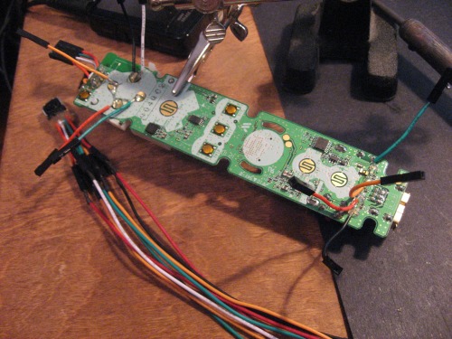
All this was done without "modding" any parts asides from removing the wii IR filter- Just gluing some pieces together.  To develop it further I will need to desolder the camera and solder lines onto the LEDs in addition I will need to create an extension interface (where the nunchuck plugs in)

Service Map for WiiDAR

WiiDAR sends commands to the Servo and receives IR data from the Wii Service.  It computes the data then sends it to the GUI.  I have been experimenting with taking those images and sending them to the OpenCV service - to extract linear information (e.g. HoughLines)


Other Ideas

  • Begin working on WiiBOT the mobile platform robot utilizing the Wiimote + Arduino and WiiDAR
  • Desolder Wii camera so it can easily be mounted in the center axis of a servo
  • A mobile chassi will be controlled by the PC via bluetooth and the WiiMote.  It is AMAZING all the sensors and controls which can be used/hacked on the WiiMote.   Commands from the computer will direct the mobile platform to turn left/right/stop/explore a new area, etc.  
    Data will be exchanged this way:  Computer -> bluetooth -> wiimote -> LED -> Arduino -> motor, servo's etc.  
    Other direction: Sensors -> Arduino -> I2C -> Extension Port -> bluetooth -> Computer
  • Another step is to get SLAM working - This will allow the robot to create and update a map and navigate within it.
  • Tilt the WiiDAR for 3D mapping.
  • Try encoder with twice the resolution
  • Mechanical step down of servo - so each position = .5 degrees
  • Double or quadruple the number of lasers - keep pulsing them to avoid cross-overproblems
  • Fix the warping do to wii camera not being mounted on servo axis


Development and Previous Failures


Here is the Sketchup I did which helped me figure out the process.  There is a 1024 X 768 virtual screen on the IR camera in the diagram.  In this sketch there are 3 blocks that are ranged.  The laser is at a constant 64.5 degree angle. If the camera finds the reflected spot @ 58 pixels - this corresponds to an angular measurement.  

So for any reflected dot you have the 

  • angle of the laser 64.5
  • distance between the laser & camera 4"
  • and angle of the ranged dot relative to the camera - initially provided in pixels

This is the old Angle-Side-Angle triangle.  Solve it, and you will have the distance from the camera to a block.

trig_png.jpg


Here is the function (in Java) to solve for distance.
  public double computeDepth(IRData ir) {
    // int pixels = 1023 - 473;
    int pixels = 1023 - ir.event.getAx();
 
    // range point
    double A; // laser static angle
    double B; // camera angle
    double C; // point's angle
 
    double a; // this is what I want, it "should be" distance from the wii camera
    // double b; // distance from the laser - don't care
    double c = 4// distance from camera to laser
 
    A = Math.toRadians(61.5);
 
    if (pixels > width / 2) { // obtuse triangle
      B = Math.toRadians(90 ((pixels - width / 2/ pixelsPerDegree))
    else {
      // acute triangle
      B = Math.toRadians(90 ((width / - pixels/ pixelsPerDegree))
    }
    C = Math.toRadians(180(B + A);
 
    // Law of Sines, like stop sines
    a = (c * Math.sin(A)) / Math.sin(C);
 
    return a;
  }


MK.1 
Pros - simple mechanical design, just mount the laser pointer on a servo
Cons - math is more complex, but worse is the fact that as the angle sweeps the resolution varies, had problems syncing servo with IR event


MK.2 
Pros - encoder could possibly have higher resolution if I used both channels
Cons - math is more complex, but worse is the fact that as the angle sweeps the resolution varies,
used only 1 channel which had 300 slots (so this was worse resolution than a servo which is about 1 degree)
In this design and previous the “ends” of the sweep became highly distorted due to change of momentum of the servo
and lag time between telling the servo to move and receiving an IR signal.


MK.3 
Pros - encoder could possibly have higher resolution if I used both channels - movement is smooth
Cons - only 20% of a revolution is used - (100% would be used if the wii camera was also mounted on the motor - with 360 degree view - similar to the Neato XV-11)  Motor spun too fast, even with 5V and low PWM data from encoder was overwhelming.  Taped 75% of the encoder up to make it less "chatty"  Potentially, this could be a good design
 
Current Design
MK.4
Pros - Camera mounted directly to the laser - both mounted to servo, problems with jitters at the end of sweeps are eliminated.  Math is simpler.  Resolution is constant instead of always changing. 
Cons - Camera not mounted in center axis of servo due to balancing problem.  This can be solved by desoldering the camera and mounting the camera on an I2C umbilical cord with the wii body behind.
Previous Software Failures
 
 
Left screen is data directly from the wii camera, right screen is beginning of interpolation.  The XY coordinate seemed
to be a bit "off".  Turns out the camera is really mounted upside down DUH, right is left and left is right, up is down, etc.
The line segments represent horizontal disparity between samples, this is the first step to determine range.


Can see some of the bad distortions at the end of this sweep ... it is supposed to be a "straight" wall.


https://www.youtube.com/watch?v=7KVii1dCVMg?hl=en

WOOOO ! This is a great

WOOOO ! This is a great tutorial, will have to make one when I find the time.

Good work

Loving the sound effects in the mk4 video.

Excellent proof of concept. I hope more people will follow, develop, improve and most of all: write about it!

You think you could add a diagram of the trigonometry involved? That would help a lot of people understand what’s really going on.

This is so nice, I was

This is so nice, I was looking for this moment, when someone managed to make a simple LIDAR. Great work!

I have 2 suggestions:

- since the camera is I2C, can you connect it directly to the Arduino and get the sensor data directly? That would make mapping a little bit easier on the microcontroller based robots

- there are good results of SLAM with ROS, some even use the Poor Man LIDAR (a Sharp rangefinder mounted on a Dynamixel servo)

It seems that because of the huge amount of data, mapping is hard to do directly on a microcontroller. I am starting to look around for a better robot brain, Chumby One seems a reasonable priced device (I like it because it has a graphic display, wireless networking, USB 2, I2C, 3 axis accelerometer, sound and lots of storage space). Will MyRobotLab work on Linux? I hope so…

IR range finder have always

IR range finder have always a problem outdoors. Ping not. A laser distance meter like shown below could be used. Some have even a Bluetooth interface already.

Laser_distance_meter.jpg


It must be me!

But, in your (Google Sketchup?) drawing, isn’t the laser mounted at the wrong end?

Your right

I realized it when I posted the picture, but didn’t feel like changing the drawing.  It would require a single little change to the trig function too.  Left or Right handed lasers would both work.

Wow - that is sweet !

$99 - for the DLR130K .   Seems a little slow though… I have to admit the wiimote is pretty quick (I think its design favors speed over accuracy)


Measuring Time, Max: 4 sec.
Measuring Time, Typ: < 0.5 sec

But the accuracy ! - Accuracy: +/- 1/16" (1.5 mm) (wow!), the $99 doesn’t come with blue tooth… 

It doesn’t say how what the max range is, but the one pictured on the Bosch site says 127’ !

I’d love to hack one up and mount it on a bot.  


Trig rocks !

Here is the Sketchup I did which helped me figure out the process.  There is a 1024 X 768 virtual screen on the IR camera in the diagram.  In this sketch there are 3 blocks that are ranged.  The laser is at a constant 64.5 degree angle. If the camera finds the reflected spot @ 58 pixels - this corresponds to an angular measurement.  

So for any reflected dot you have the 

  • angle of the laser 64.5
  • distance between the laser & camera 4"
  • and angle of the ranged dot relative to the camera - initially provided in pixels

This is the old Angle-Side-Angle triangle.  Solve it, and you will have the distance from the camera to a block.

trig_png.jpg

Here is the function (in Java) to solve for distance


public double computeDepth (IRData ir)

{

int pixels = 1023 - ir.event.getAx();

// range point
double A; // laser static angle
double B; // camera angle  
double C; // point's angle

double a; // this is what I want it "should be" distance from the wii camera
//double b; // distance from the laser
double c = 4; // distance from camera to laser

A = Math.toRadians(64.5); 

if (pixels > width/2)
{ // obtuse triangle
B = Math.toRadians(90 + ((pixels - width/2)/pixelsPerDegree));  
                } else {
// acute triangle
B = Math.toRadians(90 - ((width/2 - pixels)/pixelsPerDegree));  
}

C = Math.toRadians(180) - (B + A);

// Law of Sines
a = (c * Math.sin(A))/Math.sin(C); 

return a;

}


Supposedly a genuine, OEM

Supposedly a genuine, OEM Wiimote for under $25 shipped if anyone is interested.

Thanks for the suggestions Ro-Bot-X

I would be interested in accessing the I2C directly at some point.  In fact I will be checking this out soon, but in the other direction.  Since the wiimote sends the data over bluetooth, I wanted to get the Arduino talking to the computer through I2C -> Wiimote -> bluetooth -> computer.  The I2C directly from the camera would be interesting too !  I think the wiibrew site has info on I2C data coming from the camera and If I remember correctly Robot-Freak interfaced it already … here it is.

Interesting links. I’ll be looking into details of an implementation of SLAM shortly. 

Chumby looks like a capable uC brain - If it can run Java which it looks like it can 

http://wiki.chumby.com/mediawiki/index.php/Java - then it should be able to run MyRobotLab.  MRL was built on Linux.


I AM !

I can envision a swarm of WiiBots running around the house, mapping it, cleaning it, baking cookies !  Bwah ha ha !  Wii-Swarm!

Separation… But Success???

Finally !   Thanks to TinHead for the suggestion of using coax cable for solder wick… Didn’t have copper shielded coax, but I had some 26 awg stranded… 

  • strip
  • flux
  • heat
  • wick

3 hours of it… Finally… We have separation… But the big question is … WILL IS STILL WORK?  Going to start on the umbilical cord tonight…

IMG_0011.jpg

If the umbilical cord works, the mechanical aspects should become much more simple...

Time to test…

Operating table

IMG_0015.jpg

Camera - feel pretty good about it fairly easy

IMG_0016.jpg

Board - was a serious PITA ! - Lost a solder pad to in desoldering... we'll see if it worky..

Test time.

Thanks Gareth

And thank you for your magical elves and their 25 soldering tips

Wii camera on umbilical, 4 LED output, 4 button input

IMG_0001_1.jpg

A wii bit closer to the WiiBOT

Gareth, your elves do nice work. Or at least I have tested 1 LED successfully.

I’ve done the following:

Computer/MyRobotLab (Flipped on/off LED command) —> BlueTooth ----> WiiMote (LED) —> Arduino Data Pin On/OFF

Yay !

Off course, when I see a blinking LED the first thing I think of is, "Why that could be serial communication"

So, I’m now looking at rxtx source code to see if I can “create” what they refer to as a “CommPortIdentifier”.  The rxtx package has always worked well with real serial/parallel ports… but I have never “faked” it out with a bogus LED-serial port…   I’ll keep you posted, since I think the LED - bluetooth wireless communication of the wiimote might be fun for you to play with…

Starting an implementation (I think)

This is hurting… its a serial communication over a serial communication… yarg ???   Hopefully the sub-layers of serial blue-tooth & flashing led - can support a decent surface layer baud rate for LED-Serial

Ah, this is outstanding.

I have no idea how this escaped my notice for so long! Yet another device with the potential to clog my project pipeline. I love it.

Weird thought

Somehow it amuses me to think that some wii game programmer programmed a game to accept cheat codes (special key combo - in rapid succession) … and serial communication over the button is the same thing, except your fingers would get really tired quickly…

Serial Communication over WiiButton !

Bye Jove… I “think” this is possible (maybe)…

So I hacked together a BinaryDriver, BinaryCommPort, and a LineDriver in RobotLab…

It follows the same outline as RXTX components used in Arduino IDE-> Arduino and Processing->Serial communication

The Wii Service in RobotLab knows how to drive a line (LED) to 0 or to 1.

So I threw a little program together which I think is getting closer.  Here “writing some info to the wii” looks like this

Looks kind of Serial'esque no?   Now I'll have to look into real timings and some of the icing of serial (stop bits etc)...

I think this is like creating a Software UART, and one of the possible biggest problems is to be affected by the scheduler and be swapped off at some critical time.  I'm hoping the speed of the computer is "so wickedly fast" that a low baud rate (9600) would not be effected...

Time to do some math now...