Whirligig revisited

Some of you might have read my post on Whirligig https://www.robotshop.com/letsmakerobots/node/16995 and its predecessor SEA RENDERING https://www.robotshop.com/letsmakerobots/node/21098, and know that it was original designed to measure depths in lakes.
When SEA RENDERING took its place I felt a bit sad for Whirligig as it never had a chance to prove itself.
Then during our stay in Årdal to measure up the Riskedalsvatnet (a small lake) my brother and I had a long talk about possible reuses for Whirligig and this is what we are building at the moment.

Whirligig, -a self positioning buoy

And here are some of the design goals of Whirligig;

  • The buoy is to be lunched from the shoreline and go to a predefined waypoint using GPS and compass.
  • When it reaches the waypoint, the motor will be stopped and the buoy will drift within a preset radius of 5,10,20 or 50m from the waypoint. When exiting this ‘parking zone’ Whirligig will restart its engine and go back to the waypoint.
  • New waypoint coordinates can be issued from a PC on land using XBee communication.
  • Whirligig will constantly update the PC  with GPS coordinates and other information as long as its within reach and a connection is established.
  • Whirligig can also be driven manually via the control panel (PC) over the XBee communication, returning information on compass course, speed, rudder angle GPS coordinates etc.

The buoy itself has no purpose if it hasn’t got a mission and here is where the probe and pulley system comes in.

One of the first jobs for Whirligig is having a probe that will be lowered down to 20m below the surface and measuring pressure (to get the exact depth), water temperature, light from the surface and light from the bottom (reflected light). The aim is to get measurement from a 20m column of water with 1m intervals. So the probe will be oscillating between the surface and the 20m target.
One dive will take about 40minutes. The hope is to have Whirligig positioned and take measurement for at least a week and the probe recording 24/7.

The new design will look something like this;
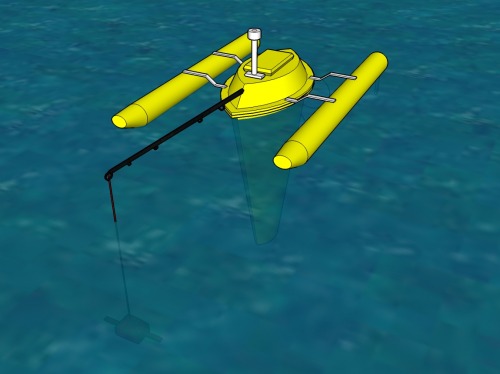
From above you se the fishing rod holding the probe away from the boat and some of its shadow.
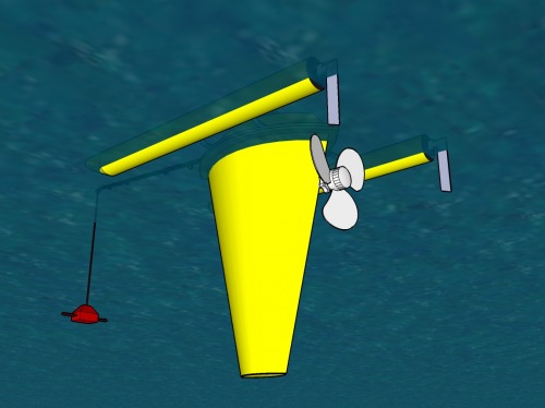
Design of the probe and pulley system.

Our initial plan was to feed power and read serial signal from the probe and storing it within Whirligig. But as the project progressed we decided to make the probe self sufficient with power and add a battery. Then storing the data on EEPROM or SD card, we were free to use a regular fishing line for the pulley system and greatly simplify the design.

The second problem was, ‘how to sense the bottom and topmost position of the probe’? Several ideas was put on the table until we came up with the idea of just using a line that has the maximum traveling length and as the motor spins unwinding the line, it will reach the maximum depth and without changing the motors direction it will start winding itself up again (a simple solution, but brilliant for our use).
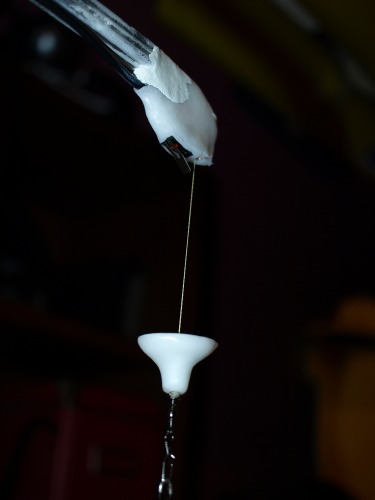
In the topmost position we have a stopper on the line and a micro switch mounted on the fishing rod, giving a signal for changing direction on the motor, and the whole sequence starts over again. The picture below showing the stopper and microswitch.

This is the motor and a spool for the line (this is only a test rig)
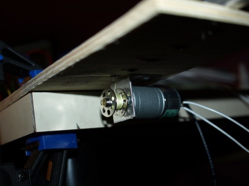
This will finaly be mounted inside the lid of Whirligig.

The control system within Whirligig has also changed considerably. From this
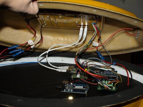
 

To this. The bottom deck is now completely empty and can host additional scientific equipment in the future.
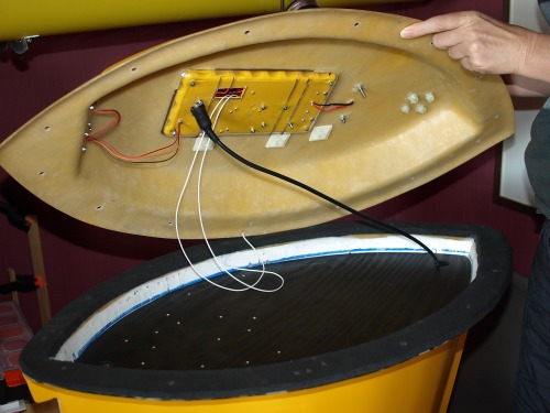
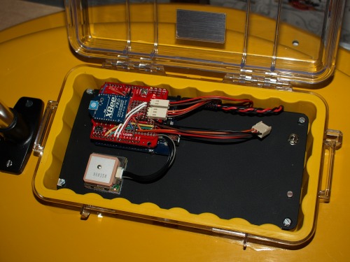
 

Underneath the black plate, the circuits for the lantern and pulley systems are mounted. On top of that we have a Arduino with  an XBee shield, GPS and a digital compass when it arrives.


Below is a screendump of the control system (with its debug window open). Written in Visual Studio Express VB.

So where is the project at?

As we already have Whirligig complete, the boat part of the project is done.
I have an idea about the fishing rod and pulley system and the circuit with at PICAXE are in place. The lantern is working  from its own board also using a 08M PICAXE.
The Arduino is reading the GPS and has control of the rudder servos and motor. I’m still waiting for the compass from Sparkfun to hook that up. Most of the Arduino code has been written and what I miss I have elsewhere in other projects.
The PC control system is almost done. I need at tab and how to control the pulley and probe.

After starting this project I have had a look at the FEZ domino http://www.tinyclr.com/hardware/1/fez-domino/ and am wondering if I should port everything over to that board.  The main advantages are;

  • Its .NET based and programmed in an IDE that is far beyond  Arduino’s capabilities (thinking of hardware debugging and intelligence for methods and objects)
  • Real string handling capabilities that makes decoding the NMEA sentences and commands from the control system easy.
  • Managed code with full garbage collection
  • Lots of more RAM and flash memory
  • I have an onboard SD card so I can log how the bouy is behaving.
  • With threading I can probably run the lantern and pulley system on different threads and thereby cut down on the hardware.

That's all for now.


Update 29/8-2010

After playing around with the FEZ Domino for a while I decided to port all the Arduino code over and use the FEZ instead.
The porting of the code took a bit of time as I wanted to move most of the code out in their own classes and get some real object oriented programming going on. That said, I absolutely love the FEZ Domino card and working in Windows Visual Studio Express 2010. It feels more robust as all UART communication with the XBee and GPS is moved out from the main program and is run by its own handlers. This means that all UART communication is run in its own thread leaving my main program free to focus on other things.

The Arduino XBee shield fits the FEZ Domino and runs straight out of the box. I had to move some of the wiring for other stuff like I2C as FEZ uses other pins for that. I also had to change a pin for the ‘probe in top position’ as not all pins on the FEZ is set up for interrupt. But then again the interrupt functions on the FEZ has built in functions like built in glitch filter, internal pull up/down and you can select interrupt on level going high or level going low or both. And the whole thing can be tucked away outside the main code. I also get real time date/time of when the interrupt occurred.

The only real issue I had was that the MOSFET for the motor didn’t fire. I think it comes down to the fact that the FEZ is a 3.3V system (5V tolerant), so I had to add an extra transistor to pull the level up to 5V for the MOSFET.

I’ve added a little video of the winch test. This is only a test rig as I’m waiting for the pulleys and spool to be fabricated.
Al in all the project is coming along very well and I believe I will be able to do a water test in a month or so.

Self positioning buoy for scientific use

  • Actuators / output devices: 600 RPM 12V motor and propeller
  • Control method: autonomous and manuell control
  • CPU: Arduino, maybe FEZ domino
  • Operating system: C++, C#
  • Power source: 12v SLA
  • Programming language: C++, C#
  • Sensors / input devices: GPS, xbee, digital compass
  • Target environment: Water

This is a companion discussion topic for the original entry at https://community.robotshop.com/robots/show/whirligig-revisited

Great!

An other great project from you my friend,with lots of informations,great pictures and also VERY inspiring. Thanks for sharing,it’s always a pleasure to read and watch your great creations.  :slight_smile:

Thank you for your kind words and positive comments

That’s why I love LMR and the people here that make this site so interesting. I’ll update this post as the work progress and add some video when we get Whirligig in the water.

Awesome

The overall design of this project is so impressive, that I hesitate to bring up a tiny detail. But you choose to hang with us nitpickers. So here you go.

The micro switch seems flimsy. It might be triggered at the slightest touch. A bit of weed floating in or on the water will get entangled on the line an it will be hoisted up against the switch.

I love the super simple control system of the probe, the yoyo winch. And I’d hate to see it malfunction on a silly piece of algae.

I’d love to offer an alternative that is equally simple as the switch. The obvious thing would be a switch that is less sensitive. A macro switch.

The second idea would be a weight measuring device in the rod. Not as simple, but is might work. When the probe is lifted above the water, its weight will increase considerably. Should be fairly easy to sense. Perhaps even in the winch motor’s current draw.

Two thumbs up for this project though. Even if the switch jams on occasion.

Thank you for your input

Thank you for your input Rik, and I do agree with you on the micro switch. 
The fact that the micro switch might misfire ones in a while is not critical to the mission as all the data will be interpolated later. And all a misfire does is cut this trip to the bottom short and the next trip will probably be the complete length.

I’ve had several ideas on the switching, ranging from a whit shrink tube on the line and an optical sensor, to hanging a magnet on the line and use a reed switch for the trigger. But none seem practical and easy enough for me to build.

Your idea of measuring the weight when it is lifted clear of the water was new and interesting but more complex, and I don’t know the weight of future probes and was planning not to lift them out of the water as my motor can handle about 450g at maximum. The target weight for the probe submerged is at 200g.

Switching from Arduino to

Switching from Arduino to FEZ domino should be very easy. OK, you have to learn a lot at the beginning, when switching to a new platform. But if you are familiar with .NET this should be an easy step. Porting the Arduino code will maybe a challenge, but most of the libs and drivers exists on both platforms.

The GPS Shield will need to be modified to work with the FEZ Domino, because the digital pins 2 and 3 are reserved for I2C bus. On the other side you have 3 Hardware UARTS on the FEZ domino available. It should also be possible to replace all the extra processors with it.

Good luck.


Now I know what the thin

Now I know what the thin wire that you do not need was for :slight_smile:

Really cool project as always, thanks for all the material, Geir!

I see

I understand that an interrupted trip down is not as serious as I thought *). I envisioned a bot in the middle of a lake with its probe dangling 10+ meter below its belly, not knowing what to do because the switch was jamming. *)

Could whirligig still travel with a dangling probe? )


) insert your own rude acronym here.

You sparked an idea Rik !

Whirligig could be running even if the probe isn’t in ’park’ position, but you should get a warning in the control panel.

The winch board has the following logic built in to it.
One pin controlled by the Arduino triggers the oscillating and as long as it’s high the oscillating will continue. When the line goes low the run has to be complete before a ‘park’ signal is sent to the Arduino (a different pin goes high). Then Whirligig is free to move.
The plan was to only have Whirligig move when the probe is in its highest (park position) thus avoiding the line getting into the propeller.

But your comment made me think… what if the line breaks and we never get the park signal, or the probe/line gets stuck somehow?
Then it struck me, why not mount the fishing rod in the back? Then we are free to move even if the system is oscillating. A small detail, but it might make all the difference when Whirligig is left on its own for a week.

Thank you Rik !!

I’m quite familiar with

I’m quite familiar with .NET and the Visual Studio IDE as I’m a professional programmer and have been working with ASP.NET sins its first release. I have only worked on web applications but the framework is not new to me.

I’m still waiting for my FEZ Domino from Sparkfun and looking forward to test it out. I have read some of the documentation and it looks like the FEZ has a great potential.
That said I had a look on their GPS driver and where not that impressed http://www.tinyclr.com/downloads/Extension/FEZ_Extensions_GPS.cs As far as I can see there is no validation of the checksum, nor does the object give you an indication of how old the GPS reading is so you could navigate on stale data. So one of the first things on my agenda is to write my own GPS driver (and maybe incorporate methods like Distanse_to and Cource_to from http://www.maartenlamers.com/nmea/ )

What I really hate with the Arduino is that the only debugging option you have is to print to the serial port, and when your serial port is used by some equipment it makes this option practically useless.

I’m really looking forward to get some hands on experience with the FEZ Domino and hope more LMR-users gets on the .NET micro framework as I think it’s got great potential for robot building.


Thank you Fritsl, you

Thank you Fritsl, you obviously keep a close watch on the forum, -and yes this project was what I wanted the thin wire for. As it turns out I think the new design will work better with a self-contained probe operating independently from the mother ship.

Makes me want to go buoy

Makes me want to go buoy hunting in Norway. :slight_smile: I have to make a boat to…

Maybe I should add a GPRS

Maybe I should add a GPRS shield so it send me the GPS coordinates via SMS on power up, and if the location shows up in the Netherlands, I know who to contact :smiley:

contingencies

I like brain storming like this. Your designs and pictures make it easy to imagine the setup.

If we’re planning for disaster, I have some more doom scenarios on the brain.

Line breaks, do you lose the probe? How about making the probe buoyant? Will be tricky to sink a buoyant probe I suppose, but you stand much better chance of (ever) retrieving it again. I might wash up on the shore and be found by someone some day.

Maybe the line had better be super strong (as well … or … instead). But if it gets entangled on whatever on the bottom your boat will not move. Could be detected at least by smart programming. Running the prop but not changing position would be a strong hint. Better not waste your battery on resisting that. Try calling for help instead.

How often will you be probing waters with less then 20m depth? That might be risky. And te only drawback of a yoyo winch with fixed length cable.

The location for the survey

The location for the survey would probably be selected based on the contour of the bottom.  Say for example Riskedalsvatnet that we measured up this summer. It goes down to about 20m and stays flat on this depth more or less the complete lake. In this case I would presume that we would add a buffer and only use a 15m line. There might still be something on the bottom to snag the probe, but hopefully we’ll be alright.

The design of the current probe is at this moment very sketchy and would probably be built with off the shelf equipment to cut some cost. I’m pushing my brother on going for the FEZ Domino :slight_smile:
As things stands now; -I would rather lose the probe then the boat. 

I have also had some thoughts about making the probe buoyant and have some sort of mechanism release a weight to let it float to the surface. One though was having the weigh on an easily corroded metal wire http://en.wikipedia.org/wiki/Sacrificial_anode but this would be hard to predict when the probe would surface.
Another thought that I had was using a 9V solenoid I have that is used for door locks, and make a circuit that would release it after a set time no matter what.

Chemical fuse timer

Original idea to use an anode as a timed release device. But, indeed, impractical. Every alternative I come up with is more complex.

First I thought of a weak(er) link between dead weigth and probe. If probe gets stuck, hopefully, the connection between weight and probe would sever, not the main line. If the main line breaks, probe with weight would sink and be lost.

How about some mechanical link that self-destruct under high water pressure? I’m sure those already exist in the marine world. Holding EPIRBs and life rafts in place.

Thank you for your input

Thank you for your input Rik, but I have no idea on how to make link that breaks under a certain water pressure. Even if I could I wouldn’t know what to calibrate it against and the depth of 20m is just a figure, it maybe more it maybe less.
For the time being I’ll just use a strong line and hope for the best :slight_smile:

It raises with 1 atm/bar

It raises with 1 atm/bar every 10 meters… If you use a nylon wire you could make a simple line cutter from a servo and some scisor like device. Unless you like long swims ofcourse :slight_smile: For the depth release thingy, you could use a hollow pipe (closed at 1 side) with a touch switch in there and a balloon wrapped arround the other side. It will need tweaking but as presure raises the balloon will try to colapse into the pipe. Untill it touches the switch.

Thank you for your input but

Thank you for your input but I think I’ll run it without a safety net. As far as I can see one of two things might happen.

  1. The line itself breaks due to wear (as the winch will go 24/7 for a long period)
    The only way to counteract this is to use a strong line and pulleys to minimize the wear.
    I’m planning to use a Fireline and a 0.39mm line has a breaking strength of 27kg and the probe should only be about 200g
  2. The probe gets tangled up in something and can’t be pulled free by the winch.
    This would probably burn the winch motor and the probe will hang there as an anchor for Whirligig. That is not that bad as we would know where the probe is an if it can’t be pulled free by hand a diver might rescue it.

One word , WOW

This project is a genius one congratulation my friend !

Thanks to share with us !

Thanks from Canada !


Michel