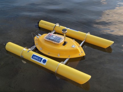
Whirligig revisited
Some of you might have read my post on Whirligig https://www.robotshop.com/letsmakerobots/node/16995 and its predecessor SEA RENDERING https://www.robotshop.com/letsmakerobots/node/21098, and know that it was original designed to measure depths in lakes.
When SEA RENDERING took its place I felt a bit sad for Whirligig as it never had a chance to prove itself.
Then during our stay in Årdal to measure up the Riskedalsvatnet (a small lake) my brother and I had a long talk about possible reuses for Whirligig and this is what we are building at the moment.
Whirligig, -a self positioning buoy
And here are some of the design goals of Whirligig;
- The buoy is to be lunched from the shoreline and go to a predefined waypoint using GPS and compass.
- When it reaches the waypoint, the motor will be stopped and the buoy will drift within a preset radius of 5,10,20 or 50m from the waypoint. When exiting this ‘parking zone’ Whirligig will restart its engine and go back to the waypoint.
- New waypoint coordinates can be issued from a PC on land using XBee communication.
- Whirligig will constantly update the PC with GPS coordinates and other information as long as its within reach and a connection is established.
- Whirligig can also be driven manually via the control panel (PC) over the XBee communication, returning information on compass course, speed, rudder angle GPS coordinates etc.
The buoy itself has no purpose if it hasn’t got a mission and here is where the probe and pulley system comes in.
One of the first jobs for Whirligig is having a probe that will be lowered down to 20m below the surface and measuring pressure (to get the exact depth), water temperature, light from the surface and light from the bottom (reflected light). The aim is to get measurement from a 20m column of water with 1m intervals. So the probe will be oscillating between the surface and the 20m target.
One dive will take about 40minutes. The hope is to have Whirligig positioned and take measurement for at least a week and the probe recording 24/7.
The new design will look something like this;
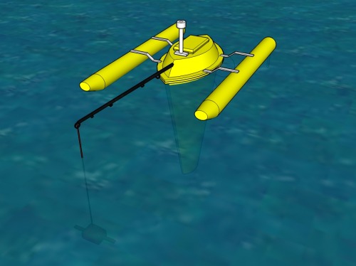
From above you se the fishing rod holding the probe away from the boat and some of its shadow.
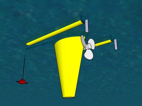
Design of the probe and pulley system.
Our initial plan was to feed power and read serial signal from the probe and storing it within Whirligig. But as the project progressed we decided to make the probe self sufficient with power and add a battery. Then storing the data on EEPROM or SD card, we were free to use a regular fishing line for the pulley system and greatly simplify the design.
The second problem was, ‘how to sense the bottom and topmost position of the probe’? Several ideas was put on the table until we came up with the idea of just using a line that has the maximum traveling length and as the motor spins unwinding the line, it will reach the maximum depth and without changing the motors direction it will start winding itself up again (a simple solution, but brilliant for our use).
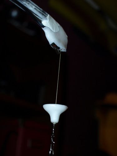
In the topmost position we have a stopper on the line and a micro switch mounted on the fishing rod, giving a signal for changing direction on the motor, and the whole sequence starts over again. The picture below showing the stopper and microswitch.
This is the motor and a spool for the line (this is only a test rig)
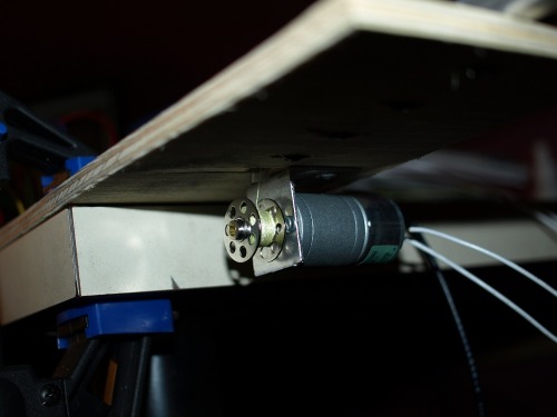
This will finaly be mounted inside the lid of Whirligig.
The control system within Whirligig has also changed considerably. From this
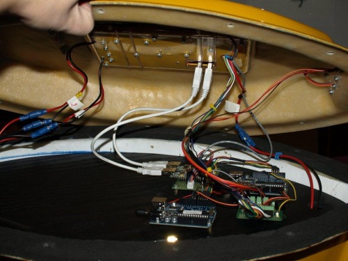
To this. The bottom deck is now completely empty and can host additional scientific equipment in the future.
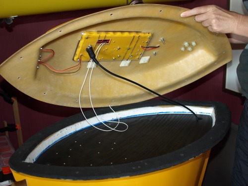
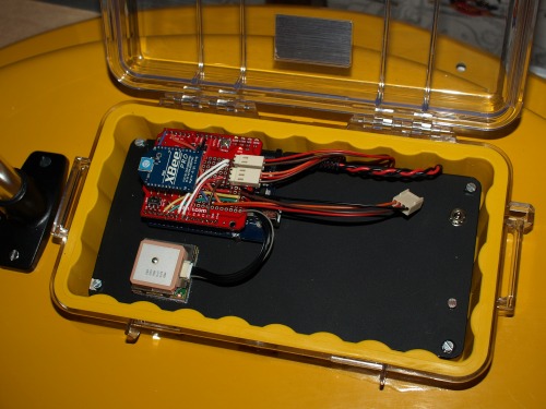
Underneath the black plate, the circuits for the lantern and pulley systems are mounted. On top of that we have a Arduino with an XBee shield, GPS and a digital compass when it arrives.
Below is a screendump of the control system (with its debug window open). Written in Visual Studio Express VB.

So where is the project at?
As we already have Whirligig complete, the boat part of the project is done.
I have an idea about the fishing rod and pulley system and the circuit with at PICAXE are in place. The lantern is working from its own board also using a 08M PICAXE.
The Arduino is reading the GPS and has control of the rudder servos and motor. I’m still waiting for the compass from Sparkfun to hook that up. Most of the Arduino code has been written and what I miss I have elsewhere in other projects.
The PC control system is almost done. I need at tab and how to control the pulley and probe.
After starting this project I have had a look at the FEZ domino http://www.tinyclr.com/hardware/1/fez-domino/ and am wondering if I should port everything over to that board. The main advantages are;
- Its .NET based and programmed in an IDE that is far beyond Arduino’s capabilities (thinking of hardware debugging and intelligence for methods and objects)
- Real string handling capabilities that makes decoding the NMEA sentences and commands from the control system easy.
- Managed code with full garbage collection
- Lots of more RAM and flash memory
- I have an onboard SD card so I can log how the bouy is behaving.
- With threading I can probably run the lantern and pulley system on different threads and thereby cut down on the hardware.
That's all for now.
Update 29/8-2010
After playing around with the FEZ Domino for a while I decided to port all the Arduino code over and use the FEZ instead.
The porting of the code took a bit of time as I wanted to move most of the code out in their own classes and get some real object oriented programming going on. That said, I absolutely love the FEZ Domino card and working in Windows Visual Studio Express 2010. It feels more robust as all UART communication with the XBee and GPS is moved out from the main program and is run by its own handlers. This means that all UART communication is run in its own thread leaving my main program free to focus on other things.
The Arduino XBee shield fits the FEZ Domino and runs straight out of the box. I had to move some of the wiring for other stuff like I2C as FEZ uses other pins for that. I also had to change a pin for the ‘probe in top position’ as not all pins on the FEZ is set up for interrupt. But then again the interrupt functions on the FEZ has built in functions like built in glitch filter, internal pull up/down and you can select interrupt on level going high or level going low or both. And the whole thing can be tucked away outside the main code. I also get real time date/time of when the interrupt occurred.
The only real issue I had was that the MOSFET for the motor didn’t fire. I think it comes down to the fact that the FEZ is a 3.3V system (5V tolerant), so I had to add an extra transistor to pull the level up to 5V for the MOSFET.
I’ve added a little video of the winch test. This is only a test rig as I’m waiting for the pulleys and spool to be fabricated.
Al in all the project is coming along very well and I believe I will be able to do a water test in a month or so.
Self positioning buoy for scientific use
- Actuators / output devices: 600 RPM 12V motor and propeller
- Control method: autonomous and manuell control
- CPU: Arduino, maybe FEZ domino
- Operating system: C++, C#
- Power source: 12v SLA
- Programming language: C++, C#
- Sensors / input devices: GPS, xbee, digital compass
- Target environment: Water


