Very simple/cheap arduino wiichuck 434MHz remote

This will get used for a small boat project (not the big boat project I work on; something to help with testing things for it).  Out in the street this is testing pretty good so I have high hopes. The boat will also have a GPS and return to near the launch area to get the signal back if it goes too far. Anyway, I know this walkthrough is little redundant as others have done similar ones, but I think this is about as simple as you can do it.

Transmitter costs about $4 and the receiver about $5 at SFE. These are 2400 baud, but you often find 4800 baud for a little more and/or ones that use 315MHz. The only difference is you would need to change the baud rate setting on both sides for a 4800.

The Wiichuck adapter is $2 or $3, I got 2 nunchucks shipped from China for $8,

I am using a Fio to transmit and a Pro Mini to receive. The Fio and Pro Mini each cost about $19.

I fitted the WiChuck adapter on the analog pins as described here and downloaded the sample sketch. It didn't work.I found other code that also failed. I did some poking around on the Arduino board and found out about the "conversation" that third party nunchucks have with the wiimote to identify themsleves. I added code for that and it works fine now.

A little Arduino programming tip is hidden in there also - note that I use elapsed time by calling millis() instead of doing a delay. The reason for that is I can add more processing into the loop and it won't affect the timing as long as I don't overload the processor. You can have lots of things firing at all sorts of different intervals somewhat independent of each other.

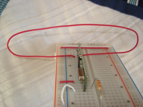
The NewSoftserial tx or rx Pin goes to the radio's data pin (just about any available digital pin will work), then power (VCC on the receiver, something between 5v and 12v on transmitter - more power = more range - I used 7.2v), GND and an antenna (scrap of wire about 7") complete it. If you do this on a mega with an available serial port, just replace RemoteTx with a reference to the Serial to use. Note that if you use NewSoftSerial and the Servo library, you may need to use Servo2 (search on Arduino boards to find out about that).

In the software, I send the letter U continuously when I have nothing else to send. It has a nice bit pattern that keeps things in sync. A few time a second I send a value,alternating between X, Y and B (buttons). I encode the number with some shifting and adding to keep it in the ascii range and make it easy to test for validity.

The packets of meaningful info are 3 bytes long. This is not a magic number but if you use long packets the error rate will rise and effective range will fall pretty quickly. If you don't feed it lots of nice clean transitions (the U character) regularly it tends to get lost after a few bytes. If you need to power off between infrequent transmissions to save power, be sure to let it spew some Us for a second or two before you send packets.

There are two projects with 2 files (tabs) each.

Here is the code for WiiChuckTx:

#include <Wire.h>

#include <NewSoftSerial.h>
NewSoftSerial RemoteTx(2,3);
#include "nunchuck_funcs.h"
int loop_cnt=0;
byte accx,accy,zbut,cbut;
int ledPin = 13;
void setup()
{
    Serial.begin(19200);
    RemoteTx.begin(2400);
    nunchuck_setpowerpins();
    nunchuck_init(); // send the initilization handshake
    
    Serial.println("WiiChuckTx");
}
int iNxtTx = 0; // 0 = X, 1 = Y, 2 = B
unsigned long lastPosTx = 0;
void loop()
{
  if( (millis() - lastPosTx) > 100)
  {
    nunchuck_get_data();
        accx  = nunchuck_accelx(); // ranges from approx 70 - 182
        accy  = nunchuck_accely(); // ranges from approx 65 - 173
        zbut = nunchuck_zbutton();
        cbut = nunchuck_cbutton(); 
    byte iVal;
    byte iCode;
    switch( iNxtTx)
    {
      case 0:
        iVal = nunchuck_joyx();
        iCode = 'X';
        break;
      case 1:
        iVal = nunchuck_joyy();
        iCode = 'Y';
        break;
      case 2:
        iVal = (nunchuck_zbutton() << 4) + nunchuck_cbutton();
        iCode = 'B';
        break;
    }
    RemoteTx.print(iCode, BYTE);
    RemoteTx.print((iVal & 0xf) + 'a', BYTE);
    RemoteTx.print((iVal >> 4) + 'a', BYTE);
    iNxtTx++;
    if(iNxtTx > 2)
      iNxtTx = 0;
    lastPosTx = millis();
  }
  else
  {
    RemoteTx.print('U', BYTE);
  }
}
-----there is a second tab named nunchunk_funcs.h
/*
 * Nunchuck functions  -- Talk to a Wii Nunchuck
 *
 * This library is from the Bionic Arduino course : 
 *                          http://todbot.com/blog/bionicarduino/
 *
 * 2007 Tod E. Kurt, http://todbot.com/blog/
 *
 * The Wii Nunchuck reading code originally from Windmeadow Labs
 *   http://www.windmeadow.com/node/42
 */
#include <WProgram.h>
static uint8_t nunchuck_buf[6];   // array to store nunchuck data,
// Uses port C (analog in) pins as power & ground for Nunchuck
static void nunchuck_setpowerpins()
{
#define pwrpin PORTC3
#define gndpin PORTC2
    DDRC |= _BV(pwrpin) | _BV(gndpin);
    PORTC &=~ _BV(gndpin);
    PORTC |=  _BV(pwrpin);
    delay(100);  // wait for things to stabilize        
}
uint8_t ctrlr_type[6]; 
// initialize the I2C system, join the I2C bus,
// and tell the nunchuck we're talking to it
static void nunchuck_init()
byte cnt;
Wire.begin();
            
// init controller
delay(1);
Wire.beginTransmission(0x52); // device address
Wire.send(0xF0);        // 1st initialisation register
Wire.send(0x55);        // 1st initialisation value
Wire.endTransmission();
delay(1);
Wire.beginTransmission(0x52);
Wire.send(0xFB);        // 2nd initialisation register
Wire.send(0x00);        // 2nd initialisation value
Wire.endTransmission();
delay(1);
            
// read the extension type from the register block        
Wire.beginTransmission(0x52);
Wire.send(0xFA);        // extension type register
Wire.endTransmission();
Wire.beginTransmission(0x52);
Wire.requestFrom(0x52, 6);        // request data from controller
for (cnt = 0; cnt < 6; cnt++) {
    if (Wire.available()) {
        ctrlr_type[cnt] = Wire.receive(); // Should be 0x0000 A420 0101 for Classic Controller, 0x0000 A420 0000 for nunchuck
    }
}
Wire.endTransmission();
delay(1);
            
// send the crypto key (zeros), in 3 blocks of 6, 6 & 4.
Wire.beginTransmission(0x52);
Wire.send(0xF0);        // crypto key command register
Wire.send(0xAA);        // sends crypto enable notice
Wire.endTransmission();
delay(1);
Wire.beginTransmission(0x52);
Wire.send(0x40);        // crypto key data address
for (cnt = 0; cnt < 6; cnt++) {
    Wire.send(0x00);        // sends 1st key block (zeros)
}
Wire.endTransmission();
Wire.beginTransmission(0x52);
Wire.send(0x40);        // sends memory address
for (cnt = 6; cnt < 12; cnt++) {
    Wire.send(0x00);        // sends 2nd key block (zeros)
}
Wire.endTransmission();
Wire.beginTransmission(0x52);
Wire.send(0x40);        // sends memory address
for (cnt = 12; cnt < 16; cnt++) {
    Wire.send(0x00);        // sends 3rd key block (zeros)
}
Wire.endTransmission();
delay(1);
// end device init 
}
// Send a request for data to the nunchuck
// was "send_zero()"
static void nunchuck_send_request()
{
    Wire.beginTransmission(0x52);// transmit to device 0x52
    Wire.send(0x00);// sends one byte
    Wire.endTransmission();// stop transmitting
}
// Encode data to format that most wiimote drivers except
// only needed if you use one of the regular wiimote drivers
static char nunchuk_decode_byte (char x)
{
    x = (x ^ 0x17) + 0x17;
    return x;
}
// Receive data back from the nunchuck, 
// returns 1 on successful read. returns 0 on failure
static int nunchuck_get_data()
{
    int cnt=0;
    Wire.requestFrom (0x52, 6);// request data from nunchuck
    while (Wire.available ()) {
        // receive byte as an integer
        nunchuck_buf[cnt] = nunchuk_decode_byte(Wire.receive());
        cnt++;
    }
    nunchuck_send_request();  // send request for next data payload
    // If we recieved the 6 bytes, then go print them
    if (cnt >= 5) {
        return 1;   // success
    }
    return 0; //failure
}
// Print the input data we have recieved
// accel data is 10 bits long
// so we read 8 bits, then we have to add
// on the last 2 bits.  That is why I
// multiply them by 2 * 2
static void nunchuck_print_data()
    static int i=0;
    int joy_x_axis = nunchuck_buf[0];
    int joy_y_axis = nunchuck_buf[1];
    int accel_x_axis = nunchuck_buf[2]; // * 2 * 2; 
    int accel_y_axis = nunchuck_buf[3]; // * 2 * 2;
    int accel_z_axis = nunchuck_buf[4]; // * 2 * 2;
    int z_button = 0;
    int c_button = 0;
    // byte nunchuck_buf[5] contains bits for z and c buttons
    // it also contains the least significant bits for the accelerometer data
    // so we have to check each bit of byte outbuf[5]
    if ((nunchuck_buf[5] >> 0) & 1) 
        z_button = 1;
    if ((nunchuck_buf[5] >> 1) & 1)
        c_button = 1;
    if ((nunchuck_buf[5] >> 2) & 1) 
        accel_x_axis += 2;
    if ((nunchuck_buf[5] >> 3) & 1)
        accel_x_axis += 1;
    if ((nunchuck_buf[5] >> 4) & 1)
        accel_y_axis += 2;
    if ((nunchuck_buf[5] >> 5) & 1)
        accel_y_axis += 1;
    if ((nunchuck_buf[5] >> 6) & 1)
        accel_z_axis += 2;
    if ((nunchuck_buf[5] >> 7) & 1)
        accel_z_axis += 1;
    Serial.print(i,DEC);
    Serial.print("\t");
    Serial.print("joy:");
    Serial.print(joy_x_axis,DEC);
    Serial.print(",");
    Serial.print(joy_y_axis, DEC);
    Serial.print("  \t");
    Serial.print("acc:");
    Serial.print(accel_x_axis, DEC);
    Serial.print(",");
    Serial.print(accel_y_axis, DEC);
    Serial.print(",");
    Serial.print(accel_z_axis, DEC);
    Serial.print("\t");
    Serial.print("but:");
    Serial.print(z_button, DEC);
    Serial.print(",");
    Serial.print(c_button, DEC);
    Serial.print("\r\n");  // newline
    i++;
}
// returns zbutton state: 1=pressed, 0=notpressed
static int nunchuck_zbutton()
{
    return ((nunchuck_buf[5] >> 0) & 1) ? 0 : 1;  // voodoo
}
// returns zbutton state: 1=pressed, 0=notpressed
static int nunchuck_cbutton()
{
    return ((nunchuck_buf[5] >> 1) & 1) ? 0 : 1;  // voodoo
}
// returns value of x-axis joystick
static int nunchuck_joyx()
{
    return nunchuck_buf[0]; 
}
// returns value of y-axis joystick
static int nunchuck_joyy()
{
    return nunchuck_buf[1];
}
// returns value of x-axis accelerometer
static int nunchuck_accelx()
{
    return nunchuck_buf[2];   // FIXME: this leaves out 2-bits of the data
}
// returns value of y-axis accelerometer
static int nunchuck_accely()
{
    return nunchuck_buf[3];   // FIXME: this leaves out 2-bits of the data
}
// returns value of z-axis accelerometer
static int nunchuck_accelz()
{
    return nunchuck_buf[4];   // FIXME: this leaves out 2-bits of the data
}
here is the receiver:

All it does right now is print the received values to the serial port, but I think/hope you could figure out what to do with them from there.
here is the file -- WiiChuckRx
#include <NewSoftSerial.h>
#define rxPin 2
#define txPin 3
#define ledPin 13
boolean ledState = false;
int counter = 255;            // To slow down the LED blinking
byte incomingByte = 0;
NewSoftSerial nss(rxPin, txPin);
void setup()                    // run once, when the sketch starts
{
  Serial.begin(19200);
  nss.begin(2400);
  pinMode(ledPin, OUTPUT);      // sets the digital pin as output
  digitalWrite(ledPin,ledState);
  delay(200);
  Serial.println("Started");
}
void loop()                     // run over and over again
{
  
// Blink the LED on pin 13 just to show we're alive
  if (counter > 0) {
    counter-=1;
  } else {
    ledState = ! ledState;
    digitalWrite(ledPin,ledState);
    counter=255;
  }
// Read from software serial.
// If any data is available, write it out through the hardware UART
  
  if (nss.available() > 0) {
    incomingByte = nss.read();
    DecodeRx(incomingByte);
  }
}
 
----------------there is a second tab named DecodeRx
byte acInBuf[3];
bool bBuffering = false;
int iBuffIdx = 0;
byte iCurX = 0;
byte iCurY = 0;
byte iCurB = 0;
bool DecodeCmd()
{
  if( (acInBuf[0] != 'X') && (acInBuf[0] != 'Y') && (acInBuf[0] != 'B'))
    return false;
  if( (acInBuf[1] < 'a') || (acInBuf[1] > 'p'))
    return false;
  if( (acInBuf[2] < 'a') || (acInBuf[2] > 'p'))
    return false;
  byte iVal = ((acInBuf[2] - 'a') << 4) + (acInBuf[1] - 'a');
  Serial.print( acInBuf[0], BYTE);
  Serial.print(":");
  Serial.println((int) iVal);
  switch (acInBuf[0])
  {
    case 'X':
      iCurX = iVal;
      break;
    case 'Y':
      iCurY = iVal;
      break;
    case 'B':
      iCurB = iVal;
      break;
  }
}
bool DecodeRx( byte inByte)
{
  if (!bBuffering && (inByte == 'U'))
    {
      return false;
    }
  else if (bBuffering)
  {
    if( iBuffIdx < 3)
      {
        acInBuf[iBuffIdx++] = inByte;
        return false;
      }
      else if (inByte != 'U')
      {
        iBuffIdx++;
        return false;
      }
      else
      {
        bool bRet;
        if (iBuffIdx == 3)
        {
          bRet = DecodeCmd();
        }
        else
        {
          bRet = false;
        }
        bBuffering = false;
        iBuffIdx = 0;
        return bRet;
      }
  }
  else
  {
    acInBuf[0] = inByte;
    iBuffIdx = 1;
    bBuffering = true;
    return false;
  }
}
That's it.
It is a real working example about to placed into service.


Well done I will have to

Well done I will have to make one of these sometime soon.What kind of range to you get on this?

Just walking around my

oops was trying to reply…

Just walking around my

Just walking around my street testing I haven’t tried more than maybe 200’. I hope to get twice that on open water. On the product page, they claim to have gotten as much as 500’. There are 2 things that factor in - antenna (the 7" or so is a quarter wave) and transmit power. Note that the receiver uses VCC but the transmitter can take anything from 5v to 12v. I am using 7.2v in testing, but will probably use 7.4v or 9.6v in actual use. If you search, you will find this is not the first or only walk through on either the radios or the nunchuck and a couple have a lot more info on specifics of the radio and how to use them with checksums for more accurate data. I went for simple as possible.

The first 2 nunchuck tutorials I tried did not have the code to adapt for 3rd party products, so I found that and worked it in. That is another reason I posted. If you get a nunchuck and it doesn’t work with one of the common sketches, try this one. Of curse, my standard disclaimer applies - “This works for me. I hope it works for you. No other warranty is expressed or implied.” ;^>

Difficult to tag this radio

The other writeups would be easier to find if they were all tagged with the same word. I used 434 and radio modem for mine. Not sure about the others.

Where do I adjust tags?

I am not seeing it in edit. I would think Arduino, 434, 315 (they are identical except the wire antenna could be shorter), radio, wiichuck, nunchuck

You may have to open the right section

See if this helps. Let me know.

Range? Plenty!

I have a pair of the SparkFun 315MHz TX/RX and I’ve been able to get up to 450M LOS with a 1/2 wave coiled antenna and 4.2V powering the TX. I guess that’d be around 1600" for you Imperials :). There’s a picture of my antenna on a blog post or something about a Big Trak, I think. Oh, BTW, the range was checked with GPS, is accurate to within 5M. I’m sure you could get lots more range with a Yagi on the receiver.


-EDIT- Found it. Bottom of the page, comments.

I have seen the SeeedStudio long range pair

This set claims 2km at a higher, but still pretty low, price. They also sell the “regular” 315 and 433 units for about $5 per pair. But the SeeedStudio long range stuff has 4 data lines and a little more complex protocol.

I have never really understood antennas well. I know that you can coil a longer antenna, but I thought it had to be done in a very precise way (like the helicoil antennas for GPS or the VHF stubbies), so I am going with 1/4 wave uncoiled. I will bend it to match the case it is going in, but it won’t go full circle. 

I did some experiments using this pair for homing with a dummied up RSSI by using really short antennas, < 5v  to transmit (using one diode to drop VCC) and then counting the number of U characters in the last 100 bytes received (and was sending nothing but Us). This worked reasonably well, losing signal completely at about 50’ and getting steadily stronger as I got closer. Those antennas where about 2". I was trying to solve a “last 50’ problem” with homing between 2 GPS units. I have since found that on open water with 2 SIRFstar III modules, I get so close that just slow circling and trying again if an apparent gap opens works pretty reliably, so I decided to use this pair for a personal RC project instead.


Yes that helped. I figured I

Yes that helped. I figured I was being an idiot. It made me feel a little better that I did need to expand “Additional Information” and I wasn’t blind to something in plain sight.

Those seem pretty cool!

Those SeeedStudio TX/RX radios seem pretty decent. I wonder if I’d really be able to get the full 2Km LOS or if I’d need to fit a directional antenna.

I have never understood antennas too well either. I’m more of a “try it and see if it works” kind of guy. That’s how I stumbled upon that configuration of antenna. I tried 1/4, 1/2 and 3/4 antenna made the same way, the 1/2 worked the best by far. Oh, and that was plugged into a breadboard track, wiring it normally may increase or decrease the range, normally increase but I’m not sure which as I’m already dis-obeying the rules of RF by making an antenna like that. I’m not disagreeing, just showing :).

I’m actually working on a design (made with QY4) for a directional Yagi-Uda antenna, just have to find three meters of thick wire somewhere. Will probably go buy some 2mm (12 AWG…) wire (as well as some coax) as the closet is rather void of wire coat hangers…

Your method of “dummied up” RSSI sounds pretty cool! I have a project that involves using a SF RX/TX pair as a lost model airplane locator. I will use a directional antenna, a LM386 attached to the data out of the RX, and a speaker to listen. The TX will be in the plane, lost, out there somewhere. By moving the antenna back and forth, I should be able to pick up a signal and home in on it. However, I was worried that the last ~15-20 meters would be the hard part, as the antenna would be getting swamped and no matter what direction you’d point it, you’d still hear something. Your idea is quite good, I may have to look into doing something similar.

For the last few feet of

For the last few feet of homing, the other thing people do is add an offset attenuator like this. The idea is to purposefully get slightly off the proper frequency so that proximity increases the strength detectably again.

Nice tip & walkthrough.

Nice tip & walkthrough. Maybe correct me when I’m wrong. But when you use the new style to initalize the Nunchuk, there is no need to decode the received bytes. The function nunchuk_decode_byte() is obsolete.

Interesting. It does have

Interesting. It does have the comment:

// only needed if you use one of the regular wiimote drivers
and I think the code I found to adjust connecting to it means I don’t need it. I have played with the accell_x and y values also and get reasonable readings across a range also, so from a high level it looks like everything is functional. Would I get better resolution (it seems fine now)? I will have to find some time to test this soon. 

I tried a directional antenna…

I tried attaching a directional antenna (looped dipole) to to the receiver, and tied the data out of the receiver to a speaker so that I could hear when good data was arriving. Then, I put together a little TX circuit (no antenna aside from the breadboard track, so that it wouldn’t swamp the receiver) that would transmit a short burst of data every second. I left the TX in another room about 20 feet away, and slowly turned the receiver. It was quite obvious that the antenna did make a difference. Together with the offset attenuator that you mentioned, I think you could get a fairly reliable tracking system going. I should try a Yagi-Uda for the antenna, see if that makes a difference…

How bug is your loop

How big is your loop (folded?) antenna? Picture?

I tried making a directional monopole by putting an admittedly undersized bare wire in a foil lined cup in hopes that it would pick up better when pointed in the right direction. I am space constrained in the spot where I would mount one. It would be inside the hull of a 4’ boat at the bow and for practical reasons it would need to be inside an area about 8" square.

It is about 11cm across,

It is about 11cm across, about a 23cm length in all for a 1/4 wave antenna. For more distance I’ve found 1/2 wave works better, but that’s at the cost of less accurracy at closer distances. I’m not even sure it’s a proper looped dipole, I just made it look like what I thought it should look like. Here’s a picture, laugh all you want :).

DSC00350.jpg

Take a look at the Wikipedia entry on Directional Antennas, I'm thinking that a corner reflector might almost be the easiest to make, with a sheet of metal and a wire. However, I'm no expert in antennas, take my words with a grain of salt...

You will need a graphical

You will need a graphical frontend for the accelaration values, to see if they were correct.

You can get a better resolution, 10Bits instead of 8Bits, when you modify your code (add the 2 least significant bits from Byte 6) :

  int accel_x_axis = (nunchuck_buf[2] << 2) + ((nunchuck_buf[5] >> 2) & 0x03); 
  int accel_y_axis = (nunchuck_buf[3] << 2) + ((nunchuck_buf[5] >> 4) & 0x03);
  int accel_z_axis = (nunchuck_buf[4] << 2) + ((nunchuck_buf[5] >> 6) & 0x03);

The SparkFun modules have RSSI!

Well, while I was reading on the Picaxe forum on how to get better data transmission results, I found a post (#58) that stated that the HiMARK RX3400 IC used in the SparkFun 4800 baud receivers has RSSI built in! While the pictures in the post are of a slightly different module, it still uses the same chip. I found a datasheet for the RX3400 (actually fairly good for being from “over there”) that has the pinout, operating circuit and other bits of information. While you’d most likely have to solder to a via or pin, if you use small enough wire it shouldn’t be a problem. I want to try this, just need to finish other projects…

That is interesting. I

That is interesting. I wonder why that isn’t brought out, especially given the redundant pins the common package has. The one major problem with how I am doing the constant stream is that I monopolize the frequency in the immediate vicinity. However, I have found one thing that makes the stream a more reliable indicator of signal strength. When I stop transmitting, I start getting garbage on the other end. The downside of these cheap Tx/Rx pairs is that you always get Rx data; if there is no good signal it just tries to interpret static. Anyway, you might think that the odds of getting a U character are one in 255, but it is nowhere close to that. In my testing, I never saw more than 1 out of 100 when the transmitter wasn’t on. and it would nearly always be 0. I would get several thousand characters of garbage without any U characters mixed in. I understand why; it just isn’t likely to get the nice clean transitions with the correct timing unless there is a transmit source driving it.