van Rijn

I'm afraid I'm STILL on the Write LMR trip. It's not got tired yet.

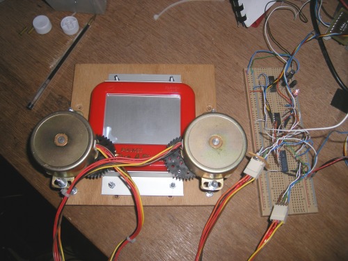
I've decided to motorise a miniature Etch-A-Sketch.

I decided on steppers. Not servos. Servos hadn't enough rotation. Continuous servos had no positional feedback.

Here's my prototype circuit. Simple ULN2803 driver and a PIC 16F628. There's a max232 on there, too as the RS-232 interface to the PC.

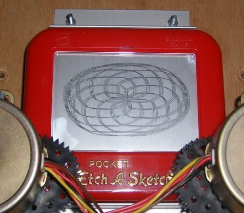
WOW! It draws a circle. The most impressive bit of this is my implementation of Bresenham's line drawing algorithm. The circle is made up of straight lines. Straight lines are more difficult to draw than you might imagine...!

Look out for more swirly patterns coming soon. Maybe even an LMR logo!

What you see in the main photo there is a "Hilbert Curve." It's a space filling curve in that the algorithm causes the "pointer" to pass through all the cells in a given area.

Hey, how weird does the inside of an Etch-A-Sketch look? I HAD to do this. I programmed it to scan back and forth so all the grey dust got scraped off the glass. It took about an hour! Hmmm... Resolution is 750x500 = 375 KiloPixels (there's a new one) x 10ms per step = 3750 seconds = 62.5 minutes.

I presume all those little metal balley things (description specially for Frits) are where the magic grey coating comes from.

Below is my attempt at a Lissajous figure with two phases. I'm happy with that.

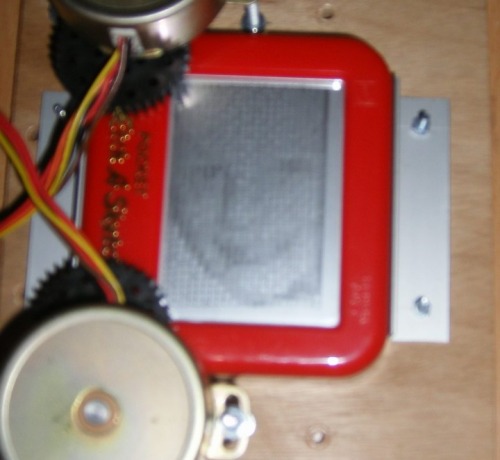
I got the machine to draw a picture of my eldest offspring. It's done by making "pixels" which consist of veritcal lines. The lines are closer together (more dense) for increasing levels of darkness. Later I will try to use a Hilbert curve to make up each pixel with an increasing "order" for increasing levels of darkness. The result should be much better, but it will be sloooooow.

This second photo is slightly easier to see the subject because it's so blurry!

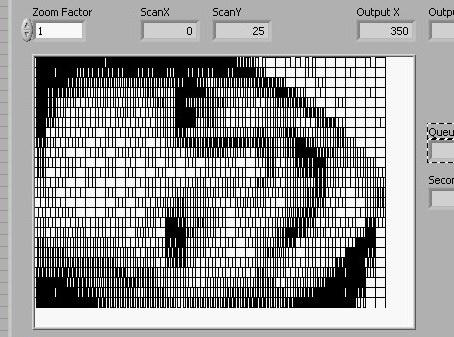
For the sake of completeness, here's the front panel of the software I wrote on the PC to control it, including a preview of the image.

I'm off to see if I can get it to draw the contents of a DXF file. How hard could THAT be?

Can you believe it doesn't EVEN Write LMR yet? How remiss of me...

Update (7-Mar-2009): NOW, it writes LMR. BTW, reading a DXF file is more difficult than I thought.

Writes and draws stuff

  • Actuators / output devices: A vector-based display screen(!)
  • Control method: Serial (RS-232)
  • CPU: 16F628A
  • Operating system: BOA-OS
  • Power source: Benchtop PSU
  • Programming language: RISC Assembly, LabVIEW
  • Target environment: My office

This is a companion discussion topic for the original entry at https://community.robotshop.com/robots/show/van-rijn

Have you thought about some
Have you thought about some multiturn trimpots?

great minds think alike

But not necessarily do alike. I spotted a similar toy myself this week and pondered about servos as well. Great to see you actually hacking into it, satisfying my curiosity.

As before with writers, the conondrum is about range vs precision. Or size vs resolution. (she said what!??)

Changing te gear ratio should give you full reach across the tablet. Worry about precision later. It takes only a very few vectors to write "LMR".

Welcome back my dear toy hacker!

8ik

Quandry
Yes. In fact, I’ve already decided that the gear seen in the photo above is not going to be suitbale. In fact, I think I’ll make it a 1:4 instead of a 2:1. Can’t immediately see a way of attaching the damn small gears to the servos, though.

Ahhh

Well, NOW I have! That’s a very real possibility.

Here’s a question: my experience of these is that the “mechanical interface” is a slotted screw. I don’t see an easy way to attach to it. Any thoughts? Have you seen others with a more useable interface?

Now THAT is the million

Now THAT is the million dollar/pound/yen question! How to mount things to other things that arent meant to be mounted there?


I have 1 here that has a tiny brass cap with a slot in. I don`t know what it takes to solder to brass but maybe you could solder or araldite a pin into the slot, which would give you a basis for fixing a sprocket on.

Good point
Brass, you say? I’d use ordinary lead/tin solder! I just need something to which I can solder it. Hmmm… A brass 3mm bolt…

Hmmm

Good point. I wanted to do this on the cheap, with stuff I already have, though.

Wait a minute. I think I HAVE steppers…


Servocity

Has some various gears in various pitch :

http://www.servocity.com/html/servo_mount_gears.html

Extending Servo Range

I recently had a project where I wanted to extend the servo range. I used 10-turn potentiometers (full size, not trimpots). You can see it on this instructable (http://www.instructables.com/id/Low_Cost_Hobby_Servo_XY_Table/) and the site (http://www.teletoyland.com/Projects/Sandbox/How_it_Works/index.php). Also, timing belts may be easier to do mechanically than gears - much wider margin for error. They make smaller timing belts than we used.


Rock on
Yep. I dug out some old Astrosyn steppers. They have very little torque, but they only draw 200mA at 12V, so I can drive them with a ULN2803. I thin kthese came out of a one-armed bandit.

Wow, that’s really cool.

Wow, that’s really cool.

have a look at this: http://blog.makezine.com/archive/2008/03/etchasketch_clock.html

The world’s best motto: When all else fails, use a bigger hammer.

Steppers
Wow! Look at those dinky little steppers compared to my monstrosities!

monstrosities

Ooh, I love that word. Kinda like: Ginormous! Don’t feel bad, You have more torque! Though I don’t know if that is good for an etch-a-sketch or not.

The world’s best motto: When all else fails, use a bigger hammer.

Nah
These are just "big." The torque on them is terrible! I had to use a 4:1 reduction gear just to get the knobs on the etch-a-sketch to turn! Hey - they were cheap!

monstrosities

Ha ha! well, cheap is good. I find several small, high torque steppers from printers myself. There are usually 3-5 steppers in an inkjet and a couple of large brushed motors. I have more than I know what to do with from just printers! Gotta love garage sales.

The world’s best motto: When all else fails, use a bigger hammer.

fantastik!!! :slight_smile:

That’s awesome!
So are you going to attach the whole thing to a giant motor that shakes it to clear the pallete?

Yes, actually

Funny you should say that, I have a third stepper for that very thing!

But this has got to the stage where I’ve proven the principle. I suffer from a disease common to engineers, where I get to a stage where I say: "Right, I’ve shown I can do that, so I don’t actually have to do it."

If you’d asked me a week ago, I’d have said I was going toetch a PCB for it, but I’m not sure if I will bother!

One thing seems likely: I want to get it to draw a curve using a RISC-coded curve algorithm. Currently the circles are a series of straight lines scripted from the PC. I want the PIC to do the donkey work.

correction

You want to SHOW that the pic can do the donkey work.

I suffer from the same infliction 8-(