Utilizing the Motor Outputs of a Servo

If you need to control a large motor but want it to have the same position control of a servo, you don't have to throw crazy amounts of money at it. You can actually have a plain old servo it self drive a large motor. This way you can feed the servo a desired position via a PWM signal, the servo tells the large motor which direction to move, and as the servo arm/pot is nudged back to equalibrium, the motor is brought to a stop.

So the first step is to take apart the servo, remove the second to last stage gear so the lever arm is free to spin yet still moves the POT. Next remove the motor, snipping the lead wires at the base of the motor. They will probably be mega short so maybe solder longer wire segments to them, drill tiny holes in the side of the servo to run these 2 wires out, then put the whole thing back to gether.

Ok, what do you do with these motor leads? The motor output of servos can NOT be directly attached to an H-bridge because the square wave output signals do not center at ground, they center at 2.5, so there is technically never an "off" moment (in the eyes of a transister). The servos do this because applying a mid voltage evenly to both sides of a motor prevents it from free spinning, this is also called, "Breaking". To use these signals in most motor driving applications, you could run both outputs through a comapator or schmit trigger to generate a new square wave that oscillates between 0 and 5.

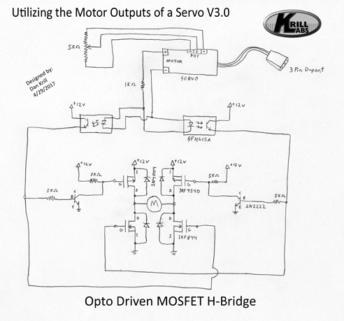
Now that your 2 control signals oscillate between the proper voltages you can attach it to anything, like an H-bridge. See the below  diagram to see an example of attaching a mosfet based h-bridge to the comparitors for a fully functional externalized servo mechanism.


-----  Updated 4-29-2017  --------

I have found that for the greatest efficiency and to reduce the chances of mosfet thermal overload, it is best to drive the h-bridge from corner to corner instead of from the same side. To do this requires a few extra components, but the results are even better!  Why this is better is because there is no chance that the p-channel and n-channel mosfets on the same side could be on at the same time. On the same-side h-bridge, during an input voltage transition from 0 to 12, there is a brief moment when both fets are on at the same time causing a direct short, allowing too much current to pass, causing the fets to heat up faster. So this corner-to-corner h-bridge prevents that.

https://www.youtube.com/watch?v=usYpLUsRRNo?version=3

Is this post missing a paragraph?

I think you may have missed a large portion of text when you posted this --maybe you didn’t get the whole thing when you did a cut-and-paste?

It just sorta starts out in the middle of nowhere, and well, sorta ends there as well. Double check your original text, I don’t think you posted all you meant to.

Just a tip

Sorry, I am new to the site, that was it actually, I was trying to help out another member of this site by giving him a tip he asked for (https://www.robotshop.com/letsmakerobots/node/20466) I thought that’s what the Tip section was for. Regardless, I added more verbage, a video, and a diagram. Hope it helps!

Very nice. Thanks for

Very nice. Thanks for posting this. 

I hope you will also post that rover project you are working on. It looks pretty amazing! 

Think of the monster servos

Think of the monster servos you can make with electric screwdriver motors and gearboxes, you’d have a ~$25 servo capable of something like 200Kg/cm 

More information please

I have been trying to run an H-bridge off a servo,with no luck.now I know why.I’m going to try the above diagram.Will it work with 7.4 volts? and could you use a voltage regulator rather than the 10k variable resistor,or is the 10k resistor the servo trim pot? With many thank to Binary bedlam

good 1

it’s kinda old but i found it helpful, didn’t know it held v on the motor for brake, that explains lots.

h bridge to the high power motor and then a mechanical link to feedback pot.

Great post

Gotta say great post. also as Amando96 said; I have a few cordless drill dead battery, they will do great with this circuit to make a powerful servo…cheapest 12 volt servo on the net is frm china at 80$, thats costly.

little confused

Are the grounds of the 12v connected to the ground of the servo controller? Probably a dumb question but very new to electronics.

last question I promise maybe

What are the 3k resistors for on the 339 outputs. Is the 10k pot for the 339 1/4watt or… I’m about to order parts and need help before making parts list.

does this cause shoot through?

Will this cause shoot through during rapid direction change. I intend on using a standard car battery for my 12v source an a shoot through would fry this in a second.

But esily said than done;

But esily said than done; using a 6volt cordless screwdriver motor gives a good power…to fix the feedback pot on the motor can be tricky.