

Hello LMRians,
Ever tried using the pololu tb6612fng dual motor driver? Quite handy if you are thinking of controlling two low powered DC motors. It can handle a peak current of 3Amps, and can deliver 1Amp continuous current to two motors. There are 16 pins on this motor driver, and here is how you connect it to an Arduino.
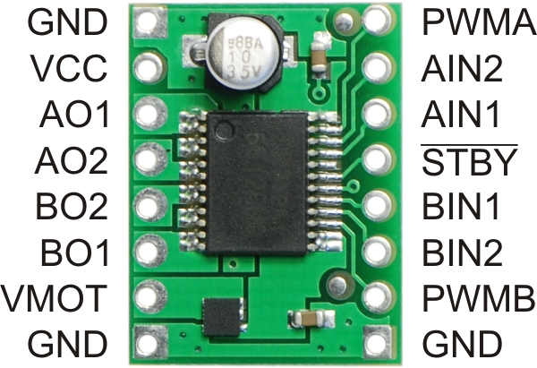
1) GND - Connect it to the GND pin on the Arduino
2) VCC - The Logic Voltage of the motor driver IC. Connect it to the 5V pin on the Arduino.
3) A01 - The output pin that is connected to the positive terminal of Motor A.
4) A02 - The output pin that is connected to the negative terminal of Motor A
5) B02- The output pin that is connected to the negative terminal of Motor B.
6) B01- The output pin that is connected to the positive terminal of Motor B
7) VMOT- The motor voltage pin. Connect it to the positive terminal of your battery. ( For powering motors)
8) GND- Connect it to the negative terminal of your battery.
9) GND- Connect it to the GND pin on the Arduino.
10) PWMB- The PWM pin of the motor driver for adjusting the speed of Motor B . Connect it to any of the PWM pins on the Arduino and specify a speed value for the motor from 0-255.
11 & 12 ) BIN2 and BIN1 - The input pins of the motor driver for Motor B that specify the direction of Motor B. Connect it to any two digital pins on the Arduino.
13) STBY- Just like a power pin which on setting to HIGH enables the motor control mechanism . Connect it to any digital pin.
14 & 15) AIN1 and AIN2- The input pins of the motor driver for Motor A that specifies the direction of Motor A. Connect it to any two digital pins on the Arduino.
16) PWMA- The PWM pin of the motor driver for adjusting the speed of Motor B. Connect it to any of the PWM pins on the Arduino and specify a speed value for the motor from 0-255.
So, now that you have connected the pins, how do you program your Arduino to control the speed and direction of your motors? It's as simple as shown below:
For motor A to go forward you need to set AIN1 to HIGH and AIN2 to LOW
likewise, for motor B to go forward, you need to set BIN1 to HIGH and BIN2 to LOW.
Swap the HIGH and LOW values to make the motors go in reverse.
Similary, for PWM, specify values from 0 - 255 to pins PWMA and PWMB,
Most importantly, set STBY to HIGH, or else, nothing will start up.
So, for driving you robot forward with a PWM value of 125, the code should look something like :
digitalWrite(STBY, HIGH);
digitalWrite(AIN1, HIGH);
digitalWrite(AIN2, LOW);
analogWrite(PWMA, 125);
digitalWrite(STBY, HIGH);
digitalWrite(BIN1, HIGH);
digitalWrite(BIN2, LOW);
analogWrite(PWMB, 125);
Similarly, for going back, swap the HIGH-LOW values for pins AIN1, AIN2 and BIN1, BIN2
In the same way, you can try out left turn, right turn, and many other functions. Good luck.
Please let me know if i have left out something, or something is not correct :-)
Ashim
