

Hi there, this is Nano Patriot; an Arduino controlled turret, ultrasonic sensor and a shooting device I built a while ago. At first I wasn’t planning on doing a write-up on this, but then I noticed Orlando_2k’s Nano turret appear on this great site generating some interesting questions in the comments section I thought I could contribute to. So here goes.
The parts
The turret I used is the pan/tilt thingy Duane Degn has talked about earlier. It fits two 9g servos. I got this lovely piece of plastic from dx.com setting me back a mere $3,45 (free shipping!). They come in four different colors, I went for a yellow one.
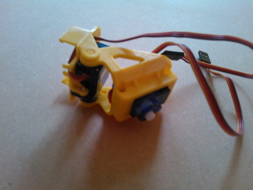
The ultrasonic sensor is an HC-SR04. I suppose I don’t really have to elaborate on that any further.
The shooting device is an R/C helicopter spare part. I got it from the well-known Chinese Store With The Rather Awkward Name. I mean this one. I got it for about 7 bucks (again, free shipping!) and it comes with twelve darts/bullets/rockets. Guess it’s supposed to resemble a Gatling gun…
To control all these wonderful electronic gems I used an even more wonderful electronic gem named Arduino Nano.
Construction
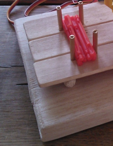
I made a little trestle in wood to fix the turret upon. I also thought it would be nice to create a little ammo stash, so I fixed four stand-offs next to the turret.
To hold the shooting device I cut some balsa wood that would just fit the Pan/Tilt-clams and I used some tie-wraps to fix the gun to the balsa wood.
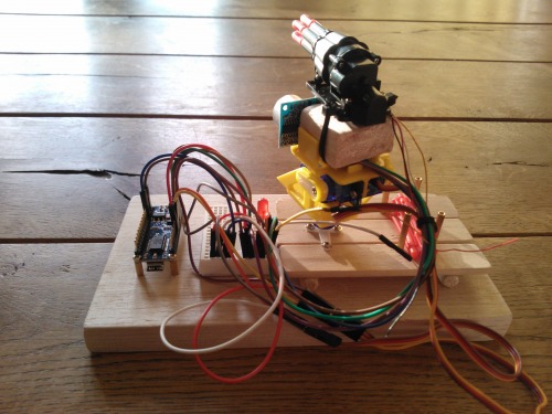
I bent the pins on the HC-SR04 90 degrees and fitted those between the Pan/Tilt thing and the wood block. I put the trestle on another piece of wood so I could put the Nano onto it along with a mini breadboard.
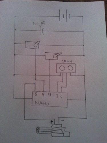
The circuit
The circuit is rather straightforward. The ultrasonic sensor goes in pins 2 and 3 and the servos in 4 and 5. The shooting device has four wires attached to it, black, red, yellow and white. With the white one wired to ground, the gun fires when the yellow wire goes high. I found it to fire a single shot every 150 ms, but I guess you’d have to experiment with each single device to find the appropriate duration. I came across some documentation somewhere stating the red wire going high when a shot has been fired, but my multimeter never detected any such event and I’m unable to find the link to that documentation again, otherwise I would have posted it here of course. What to black wire is supposed to do is still a mystery to me.
The sketch
Now there is of course a million ways to program a piece of armament like this; in the sketch attached I’ve defined three modes: Random, Scanning and Static. In Random mode it picks (you guessed it) a random x/y position and moves the servos to that position. In Scanning mode it scans the sky in a three-by-three pattern and in Static mode it just sits there doing nothing, movement-wise.
The code I drafted is in the attached zip-file on the top of this page.
In all three modes it scans for any objects in front of it at a distance between 20 and 80 centimeters (1 cm is about 0,39 inches, we have the metric system over here :D). To deal with false positives it scans three times, when two of those are equal and within range it fires. I wouldn’t bother with single shots so it fires all six rockets, moves to reload position and then goes to sleep.
Take a look at the videos if you want to see it having a go at Bob! I think Bob is a really tough dude. He didn't even winch!
Update
Orlando_2k and Duane are right: I should have added a transistor to keep the Arduino out of trouble. As I wrote, I measured the gun drawing some 47mA, which is already too much according to the Arduino documentation, but it could easily peak, for instance when a dart is jamming the DC motor or such. As I was on it, I also added a diode to protect the circuit from flyback current from the DC motor. The schema now looks like this:
The diode hiding behind the transistor:
![]()
Thanks fellas!
Update 02/27
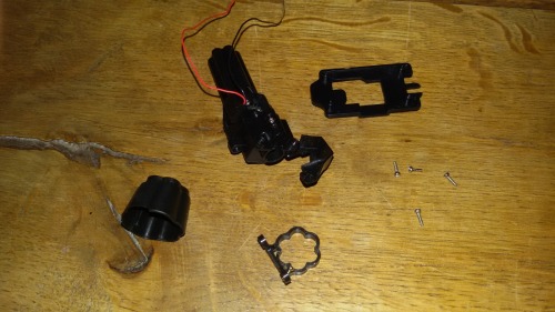
Yesterday I was toying a bit with another launcher that came in through the mail recently. I wanted to sort out the feedback signal that Yahmez commented on. Unfortunately, after a lot of breadboarding and programming it became apparent the launcher had DOAed, so I took it apart, partly out of curiosity and, as I'm somewhat ashamed to atmit, partly out of frustration... However, I learned from it. What I didn't get from Yahmez comment, is that the red and black wire simply act as a button, they connect, there's nothing more to it. So that's what "shorted together" means. As I said, I learned from it. I haven't yet figured out if I've beefed-up my knowledge of electronics or my knowledge of English :D. Anyways, thanks Yahmez!
Here's a picture of the partly disassembled launcher. Too bad I already tossed the DC motor before I thought of taking a pic.
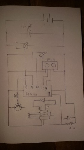
Update 03/06
Connected the feedback wires yesterday. One signal wire goes to 5v, the other is connected to pin 2 on the Arduino, the one where interrupt 0 lives. I used a 10k resistor to pull it down and added a capacitor to debounce. The schematic now looks like this:
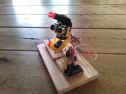
And the current build. It's already getting a bit crowded on the mini breadboard!
About the programming: I used interrupt 0 to detect a missile launched. On the RISING event the interrupt handler sets the firing pin low and counts the number of missiles already launched. If the launcher needs to be reloaded (shots fired == 6) it moves to reload position (pan servo centered, tilt servo all the way down) and goes to sleep. The third video features the Patriot in scan mode (see above) firing a single missile at the time and then moving to the next position. The shaky bit at about 15s is where I got hit point blank...
And of course the adapted code is attached.
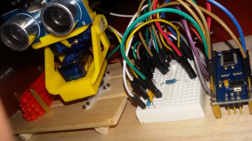
Update 04/09
As requested by Bouldr, here's a picture of the breadbord. It's quite a spaghetti, however it's all pretty simple: right tops (two lanes) is all ground, right bottom (also two lanes) is all 5V, battery wires go there as well, powering the board on the 5V pin (not recommended, I know). The middle part has a resistor leading to the transistor base and two wires carrying 5V through the transistor to the launcher's dc motor. Hardly visible is the diode protecting the circuit from flyback current coming from the DC motor. On the upper left there is the constellation pulling the launcher callback low and a capacitor to deal with debouncing.
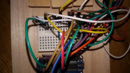
I love the guy/girl who invented schematics!
This is a companion discussion topic for the original entry at https://community.robotshop.com/robots/show/updated-nano-patriot

