I've tried looking around a bit and expect this to be a fairly basic question, but nonetheless I still can't get it to work. Basically I have an arduino connected to a SN754410 motor driver powering a lego motor. This all works fine until I try to use a second power supply (9V battery in this case) instead of the arduino's 5V output. Here's the current setup:
Note that the arduino is running off of USB power.
I’m not sure exactly how to make it run - I tried putting an led & resistor in series with the 9V as well, and in doing so I found that current is being drawn. Also, testing the 9V with the motor (directly wired) works fine. What connection am I missing to get this working?
Also, I read in a few discussions around here that the SN754410 doesn’t have kickback protection diodes - where would I add these diodes? Between the +5 and Vcc?
Thanks!
It looks like your wiring is
It looks like your wiring is a little funky. I don’t know about your breadboard, but I know mine has the two power rails on either side that run the entire length of the board. In your case it looks like the ground of your battery is connected to the ground of your arduino via the black wire on the right side. I’m almost positive that shouldn’t be there.
This breadboard is also like
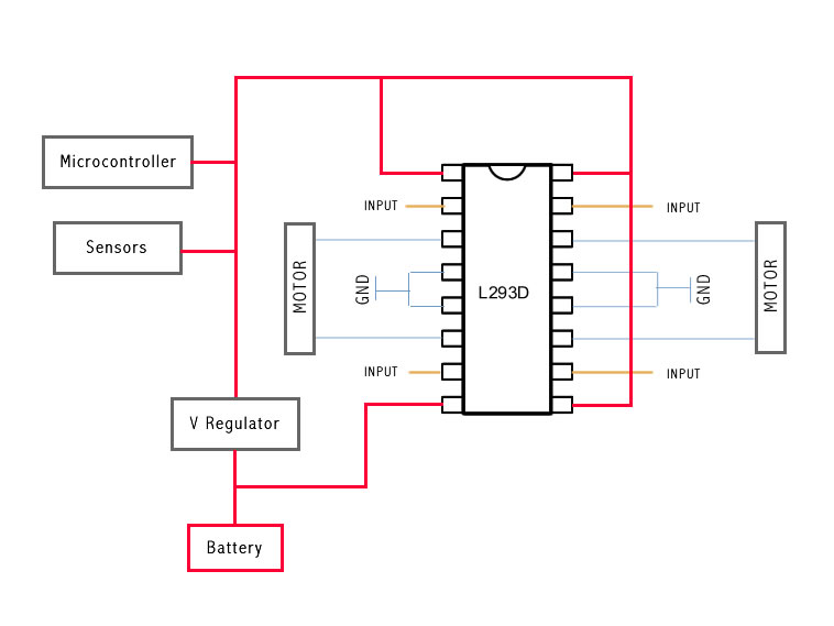
This breadboard is also like that, so yes the grounds are connected - you’re right in that its incorrect, but I don’t know how else to handle separate sources. I’ve tried it without that wire and it still doesn’t work. All the examples I’ve seen so far are setups where one source is run through a voltage regulator, such as this one:
http://farm4.static.flickr.com/3507/3235657956_3307e726bc_o.jpg
How should this chip be wired when there isn’t a common ground?
I understand
I understand the dilemma now… I’m not exactly sure what to do, but you would not have a common ground between the different power supplies. You would need one side of the motor grounded, and the other enabled by the SN754410 to make it go one way, and then the opposite to make it got he other way. So idk.
I would recommend looking at this: http://www.societyofrobots.com/member_tutorials/node/159
It’s a tutorial on how to build a motor controller that can control speed and direction of 2 separate motors using PWM. It fairly simple to build with a few 2 tri-state switches (also explained in the tutorial) and an SN754410.
Hmmm…
I recently set up an L293D with succes. It’s pin compatible with the SN754410.
I think the grounds SHOULD be connected. I don’t have any previous experience with DC motors or H-bridges, but when I power servos from an external power source I allways connect the grounds. Otherwise it wont work. So I presumed I should do the same in this case, which as I said worked for me too.
What seems odd to me is the fact that pin 1 is permanently connected to 5V while pin 2 and 7 are connected to PWM outputs?! Pin 1 should be connected to PWM (to control speed) and pin 2 and 7 should be connected to a normal digital output (to control direction). Well it should still work the way you did it however you definately wont be able to control the speed of the motor, cause it will allways be at max. (5V).
The only thing I don’t
The only thing I don’t understand about having the ground connected is that one source is 9v and the other is 5v. Having their grounds connected is like wiring them in series, yeah?
Only if you connected the
Only if you connected the volatge wires too. If you use 2 power sources the grounds MUST be connected together or it won’t work. The electrons need a way to make a complete path between both power sources.
I understand now, Thanks!
I understand now, Thanks! Well, I don’t see anything wrong with the circuit then.
It should be fine to PWM the
It should be fine to PWM the inputs instead of the enable. I have done this before. The difference is you use 1 less IO each side, but need 2 pwm pins instead of 1.
Does the circuit work if you run 5v from the Arduino to vcc2? Dont stress or touch the motor shaft because you dont want it to draw too much current from the Arduino.
Flyback diodes should be added to each motor output similar to this diagram so that 1 diode "points" from GND to motor output, then the 2nd points from motor output to vcc2. Honestly, other than the diodes missing I can`t see anything wrong with the circuit.
You’re right 
It does work like that too and since it’s simpler and uses fewer pins I decided to go for that way in my setup. So thanks for letting me know 
Actually…
…I just accidently ran the setup WITHOUT connecting to 2 grounds and it WORKED?! I know it’s not supposed to but it did…
Strange cause when I tried the same with a servo some time ago it didn’t move at all?!

MIssing the weakness
I would say that the problem is in using a 9 volt battery as the second source. These are weak, meant for limited current output. A 9.6 volt NiCd or NiMh would have enough current delivery to actually turn the motor.
Common grounds should always be used, so that the digital inputs have a reference to work from for their switching levels. Without this reference, things might or might not work depending on how levels "float" at the time.
Just thought to add, with a 9.6 rechargeable pack, there is a possibility the motor might draw enough current to cause some damage to the 754410 h-bridge. Some details about the motor might be helpful, such as any specs, ratings, or a datasheet detailing these. Or at least where it came from.


