I am trying to figure out how transistors work and have seen the three terminals on a bipolar transistor labelled base, collector, and emitter.
I am having a hard time understanding the purpose of the three, and would like it if someone could explain why they are named this way. I.e. what is basey about the base and what is the collector collecting?
At the moment they just look like three randomly chosen words.
maybe its because if u actually ground the emitter, it would render the transistor moot. the emitter is the buisness end of the transistor, the thing you connect to whatever it needs to manipulate the power for.
also you cannot rely on a transistor to ground your circuit, because it does not make a connection all the time. it switches on and off, and having it as the only ground, that would mean that when it is switched off, it will break the circuit.
also where the power goes in, it does nothing to ‘power’ the device. a transistor doesn’t need power to operate unless and until it is being used, unlike an IC which needs to actually needs to have power all the time in order to function.
Right, I have read and taken on board all the info from the comments. Thanks a lot.
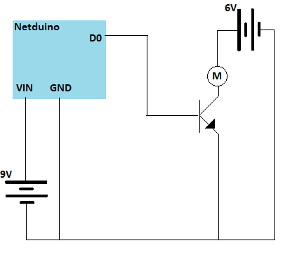
Here is what I plan to do. I want to turn a motor on and off using a Netduino. I think the motor will work best with its own power supply, hence the transistor.
Could someone please take a look at the circuit diagram below, and let me know if it is suitable and point out all my stupid mistakes.
I imagine it will probably need some resistors too, but I don’t understand where they should be or which strengths. I think the motor itself will behave as resistor.
I read somewhere that it was a good idea to use a diode to protect the transistor from some kind of reverse current. But I didn’t understand in which situations this was nessacery or where it should go.
I am concerned that the transistor says “Current Ic Max:0.1A”. while my motor ranges from 50mA to 700mA. Does this means the motor will brake the transistor?
For motors and control from an MC, I would suggest using the RFP30N06LE MOSFET which is basically the same as a Transistor but can handle much higher currents than the transistor you have.
It will also connect basically the same way, however the pins are called Gate (base), Source (Emitter), and Drain (Collector) (if I have that right).
R28 is the suggested current limiting resistor, and really only needed if you don't know what will be controlling the MOSFET (transistor) - but good practice.
R29 is a pull down that keeps the MOSFET switched OFF when no power is applied to the gate from the Netduino
R30 is a limiting resistor for the LED which lights when the MOSFET is turned ON (Even if the motor is not connected or burned out)
D7 (although not a scotty) is a fly back diode that will shunt reverse voltages from the magnetic field collaps when the motor is turned off and protects the MOSFET. Note that this should always be used with an inductor load, but not needed for a resistive load. Regardless I always include it.
In this case, the MOSFET is being used to provide ground to the motor+LED circuit thus turning the motor ON or OFF.
Thanks everyone. This is great. I feel like I understand what the transistors are up too. I have also taken out a couple of library books and am reading up some more.
I originally bought the L293D motor driver because I was building the “start” robot. I deviated from the instructions by getting a Netduino because I’m familiar with C#. When I tried to use the L293D I just had no comprehension of what it was, so started look into transistors which I could vaguely understand. I am now feeling more confident and I’m looking over the L293D datasheet again.
Could anyone post a similar circuit diagram to those below, except making use of the L293D?Ideally, I want to be able to control two motors independently and turn them both forwards and backwards.
I have searched around, but all the tutorials I can find are much too complicated and build a whole robot. I’m still struggling to just turn the motor on. I don’t understand if a second power supply is really necessary or if I’m making life hard for myself.
Thanks for your help and apologies if I am asking too much.