Greetings fellow meatbags.
Calculon is trying to hook up a pimpin motor to his Mr Basic, and has come across something very confusing with his transistor.
Here's what he's trying to do with a nte123 pulling a seperate power supply to a motor made for 3v:
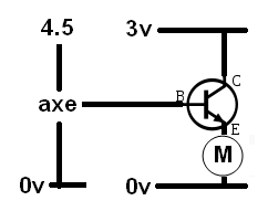
He also tried it with a 2n3904. It didna work for either. According to his understanding of NPN transistors, the output from the picaxe should switch on the tran, and pull the 3v through the motor. No?
Using an LED to see if the tran worked, Calculon accidentally made this ....
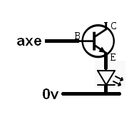
…which totally worked. This also confuses our hero. So our hero has other methods to activate the pimp motor, but he’s just wondering why these don’t/do work. Okay, go.
Just to cover the basic
Just to cover the basic stats first: the maximum current of the NTE123 is 800mA, which should be plenty for a 3V motor. The current gain in the area you’re operating will be at least 50 times, so the input current doesn’t need to be any higher than 800mA/50=16mA. The base-emitter voltage drop is 2V on a bad day, so it wouldn’t be a bad idea to put a resistor between the PICAXE output and the transistor base: (4.5V-2V)/16mA=156Ω, but anything vaguely close will help reduce the current output required by your PICAXE. Also, as you’ll see in the link Ant posted, a protection diode is a good idea.
Have you tried putting the motor between the +3V supply and the transistor collector instead?
When the transistor is turned on, the +3V will be shared across the motor terminals and the collector-emitter terminals of the transistor. The voltage drop across the motor and transistor will change depending on the current through them, and various other parameters that are a pain to examine, so we’ll just look at the maximum values. Technically the transistor can drop anything between zero and 1V across the collector-emitter terminals, so we’ll just assume the motor therefore gets anything from 2 to 3V.
Although the situation is probably never this bad, imagine that the motor is using up the full 3V, and the base-emitter junction is also soaking up it’s maximum of 2V. Working up from zero volts at ground, we have 3V across the motor, and then 2V across the base-emitter junction, so the voltage at the base terminal has to be more than 5V before it can push any current into the transistor to activate it. The PICAXE is limited to 4.5V, so it can’t turn the transistor on.
If you put the motor between the supply and the collector, then the PICAXE only has to output 2V at most, which is easy, and the motor still gets as much current as it wants.
EDIT: Man that was way to long, I won’t feel bad it you just skip to the bit where everything works just because.
thanks for th’input
You guys are awesome.
about the LED… I thought current was supposed to be unable to go directly from base to emitter …
SUBJECT GOES HERE
Afraid not Calculon, the base-emitter junction of an NPN BJT is just like a diode that will allow current from B -> E but not the other way around. In fact it is a diode. An NPN is the same as two PN diodes back to back, sharing the P-doped region.


