

COMPLETED: 2011.12.08
This is my first robot built from scratch and I am new to robotics. I haven't played with electronics for over 25 years and I have a little programmed expirience in many versions of Basic dating all the way back to the days of the TI-99 computers.
In short, I am a total Neebie in Robotics and if I can do this, anyone can too.
Started on 2009.05.02
Ever since I first read about a robot that had thermal sensors that enabled it to follow its human controller in the Summer 2007 edition of Robot Magazine, I have dreamed of building a Robot to lug around my Laptop and all of my networking tools. I also thought that it would be so cool as an IT Consultant to have built my own personal robot to carry my tools around.
Enter TOBI
TOBI used to be ToB1 for tool bot 1 but my wife liked the name so that is how the name was chosen. I decided that TOBI was going have 6 phases of developement. Each phase has a mission and will may include the functions of prior phases.
TOBI 1 - Development on the run (Completed 2009.05.29)
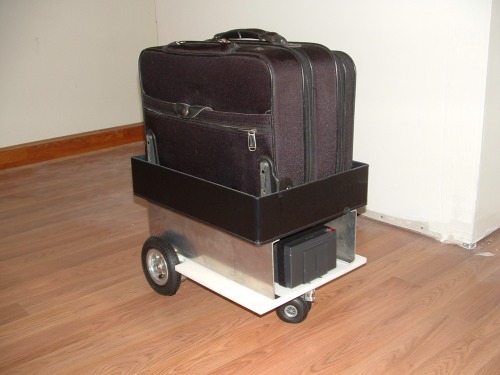
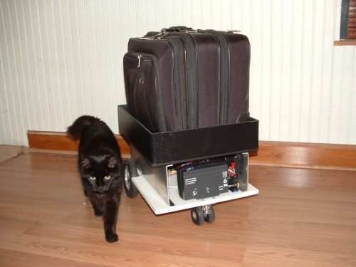
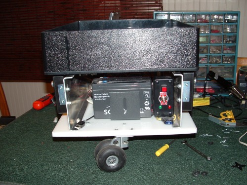
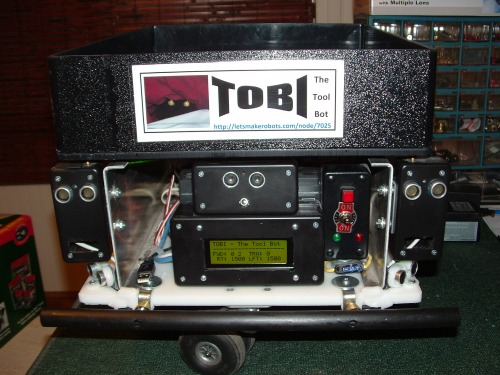
TOBI 1 will have the same Chassis as all future versions except TOBI 6. It will be able to carry my Laptop and tools (when I trust it or myself enough) As seen in the picture, it is capable of carrying my current Laptop/tool case. It will be completely remote controlled. It has no sensors and is capable of being driven into trouble like off curbs and into objects. I will use this to test the types of sensors and mounting locations for my sensors.
Parts List for TOBI 1
- Motor Mount & Wheel Kit with Position Controller
- HB-25 Motor Controller
- Wireless Control for Robotics
- Canabalized parts from a BOE-Bot Kit
TOBI 2 - Propeller conversion (completed 2009.11.14)
TOBI 2 ( ADDENDUM: Convert to Propeller Controller) ADDENDUM: Replace the BS2 controllers with the Propeller Controller. Abandon the Position Controllers and directly control the HB-25's with standard servo pulses.
Parts Added:
- Propeller Proto Board USB (Replaces the "BOE-Bot BS2")
- 12V Relay for powering the HB-25's
TOBI 3 - Semi Autonomous plus idiot proofing (Completed 2010.06.25)
TOBI 3 will be remote controlled with a new Propeller powered remote. It will be equipped with the added idiot sensors that will prevent it from running into most objects and avoid obsticles using the PING)))'s while doing it. Or it can be remotely controller just like prior versions.
ADDENDUM: The prior wireless remote system was scrapped for several reasons. The first being that the units did not have RSSI signal strength which I will use as a second mode for TOBI to lock onto the correct thermal object. The new units that I am looking to purchase run on 3.3 V [the same as the Propeller] and will enable me to make a smaller remote controller. Also they are trancievers so that TOBI can talk back to the remote. I am also getting a 3-Axis accellerometer for the remote.I had to add 2 more PING)))'s to get better object avoidance and then I added bumpers to protect the PING)))'s. Then it was a very simple addition to add the bumper sensors to them.
Parts Added:
- Bumper Switches
- 5 PING)))'s Addendum: Added 2 more for a total of 5.
- Custom built Wireless Remote Controller (using the PropChip Propeller, two new Tranciever modules and a new 3-Axis accellerometer. More info to come)
ADDENDUM: TOBI IV will be in a new project page with a new chassis and all new hardware.
TOBI 4 - Autonomous and Semi Autonomous, Remote Controled plus full idiot proofing (See TOBI IV - The Tool bot pages)
TOBI 4 will have more sensors installed. It will have new IR sensors to make TOBI more adept at avoiding obsticles and will now follow the heat signature of a human using the TPA81 Thermal Pile.
Parts Added:
- TPA81 Devantech 8 Pixel Thermal Array Sensor Array
- Several Sharp IR sensors with ADC board
TOBI 5 - Bug Sweeping
TOBI 5 will enhance the thermal sensor in TOBI 4. The reason is that, after thinking about this project for over a year before I started work on it, I came to realize that in an office environment, the thermal sensor has a serious flaw. TOBI will lock onto ANY human and follow them, so in this version I am going to add a secondary system to identify the master target from all other heat sources. At this point, I will use RF and Thermal by adding three trancievers on TOBI in such a way that it can get a directional bearing from the RSSI value of the transmission from the remote controller.
Parts Added
- 2 more trancievers or a custom directional antenna for the current tranciever on TOBI 4
TOBI 6 - The finished rolling Laptop & Tool Case
TOBI 6 is the result of the first 5 with a complete case redesign. I hope to make the case out of ABS plastic and Aluminum struts. I want a tool compartment and above that a top lid that opens to reveal the laptop storage. Also I was thinking of having the Laptop section raisable to act as a mobile work table for the laptop. At this point nothing is set in stone for TOBI 6.
Chasis Construction:
I started by measuring my current Laptop case. I decided on 15" x 18" and l looked at various materials from plastic to wood and metal for the first base. I tended toward plastic, but I was concerned about it not being strong enough. The thick cutting board plastic seemed strong enough to try for the first TOBI base. I enlisted my brother since he has a shop and builds a lot of custom projects. He went to a local plastics shop and found a scrap piece of plastic cutting board material. He also found a box made of ABS plastice that was commissioned by someone who never picked it up. The cutting board material was larger than my size needs and the box was smaller but it fits my current case. The total cost for the plastic base was $25 for both items. So the design is a simple 2 deck robot with all of the electronics on the lower deck and payload on the upper deck. Also the upper deck may have some sensors attached to it when I get to the TOBI 2 phase.
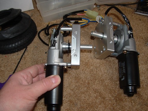
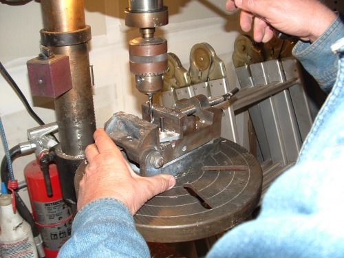
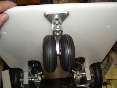
First I assembled the Motor Mount Kit omitting the Position Controller circuit board lest we damage it during the constrution of the chassis.
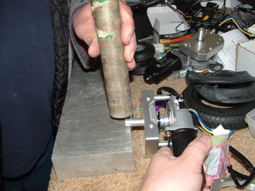
Inserting the pin in the shaft is DEFINATELY a two person job. Too easy to mess this part up if you try it alone.
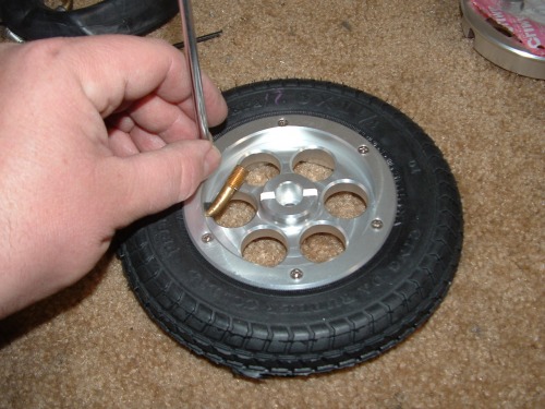
Assembly of the Wheels was fairly simple.


The first we did was cut the 1/2" cutting board material down to the same size as the the ABS plastic box dimentions.

I had decided to have my wheels indented inside the dimentions of the robot so I knew that we had to cut the board to fit the wheels dimentions.

Also this brings up a problem that others who have used this kit ran into. This is the problem that the mount is lower than the motor. So we discussed shims for the motors and the castor but I did not want it to be more top heavy and possibly unstable when carring a load. Three months ago I emailed Parallax with lots of questions as to the dimentions of this kit and to my surprise, recieved a call from a technician who spent about an hour with me on the phone answering all my questions. I wish some companies that I deal with at work were so helpful and attentive when I am dealing with a Server crash, but I digress..
I decided to cut holes in the plastic to accomodate the motors. So first we cut out the wheel area.


Next we measured where the motors would protrude through the base and cut them out.


We had to add an extra cut out to fit the motors inside the cut.
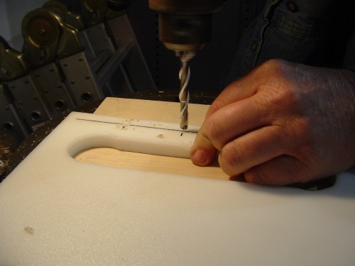
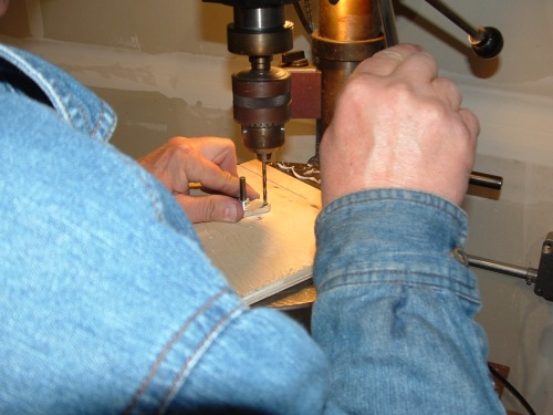
We measured where the screw holes for the motors were and drilled them.
One other issues that I had was how to suspend the upper deck above the lower deck. My brother came up with some aluminum that he had laying around from some old project that was the perfect size so all we had to do was drill holes in it. This also provides greater structural integraty for the motors and prevents (hopefully) that sway-back horse look when carring a heavy load of tools.
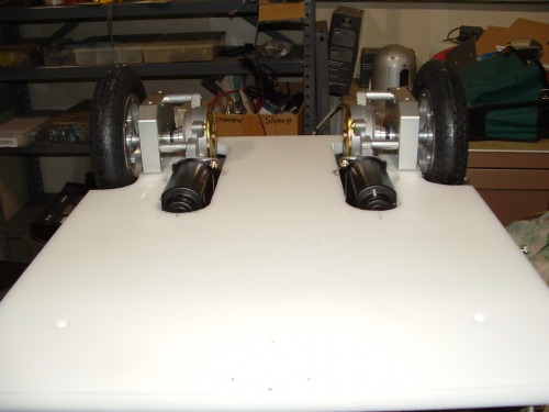
We test mounted the Motors.
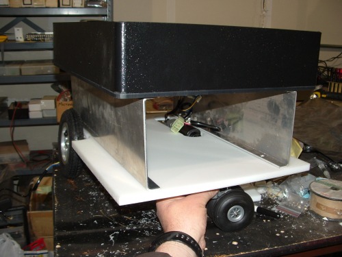
I layed the top deck on and held the caster under to get a feel as to what TOBI would look like.
My brother had really nice stanless steel screws that we used so we had to drill out the screw holes in the caster to fit.
So I flipped TOBI upside down to drill out the holes for the caster. Here is a good view of the design issue of the motors interfereing with the base and why we had to cut those holes in the base.
We drilled counter sink holes and embedded the lock nuts in the plastic.
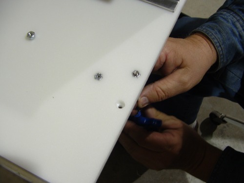
The finished undercarrage.
Next we drilled the holes for fastening the upper deck. I wanted the upper deck to have a quick release so I put bolts up through the aluminum with nuts on top and then the upper deck fits on that and another nut to fasten the upper deck or wingnut.
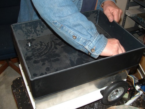
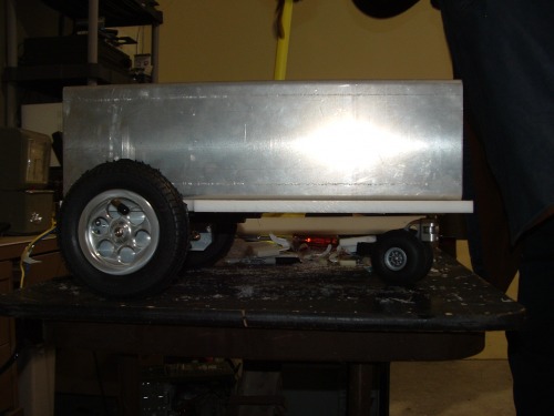
The final look of this stage of work without a payload looks like this.
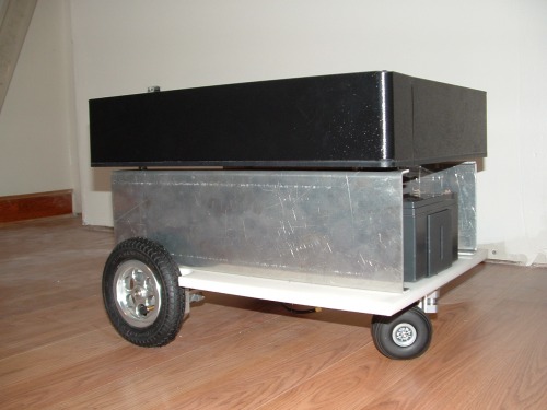

Surprisingly it actually fits my current Laptop/tool case.

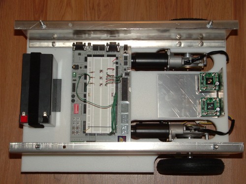
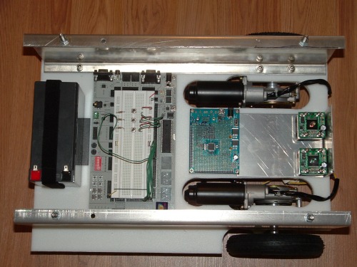
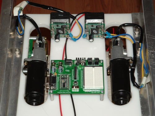
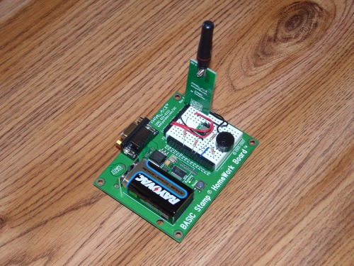
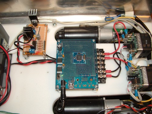
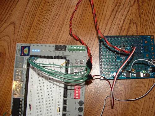
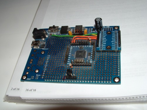
Well that was enough for one day's work on my project except to look at possible layouts for all of the circuitry. Here is a possible layout with my Development Board as the main board.
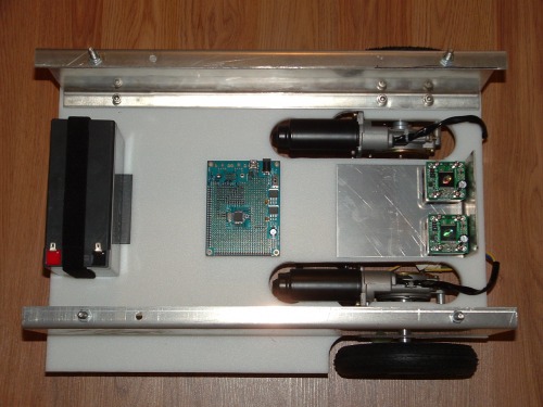
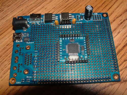
Here is the board that I bought for permanent microcontroller of this robot.
I did find that I could very easily fit both my Development Board and TOBI's controller at the same time. In this configuration, once I remove the Development Board I could use the extra space for more or larger batteries.
So the chassis is mostly complete. The Motor and Wheel kit comes with ready made BS2 code that can be downloaded from Parallax for testing the motors and HB-25's. I was hoping to reach a point to plug in the BS2 board that was in my Wireless Kit and see TOBI move 14 & 1/2 feet. Having that extra BS2 Homework board comes in handy since all of the Parallax product line have sample code for BS2.
Once I get the chassis wired and tested with the BS2, I will move on to making test code in SPIN for the Propeller chip. I also have to make the wireless interface. The one I purchased utilizes the BS2 Homework board and I want to use the PropStick to do two things. One, shrink the device size and two, to have a Propeller chip on both sides of the interface so that I only have to code in SPIN.
Well that is it for one weekend. I want to give a lot of credit to my brother Clark for the use of his shop and his experience in fabrication, not to mention the materials he donated to the project. Without him, TOBI would have never gotten his wheels on the floor.
I will post updates as I progress...
UPDATE: 2009.05.15
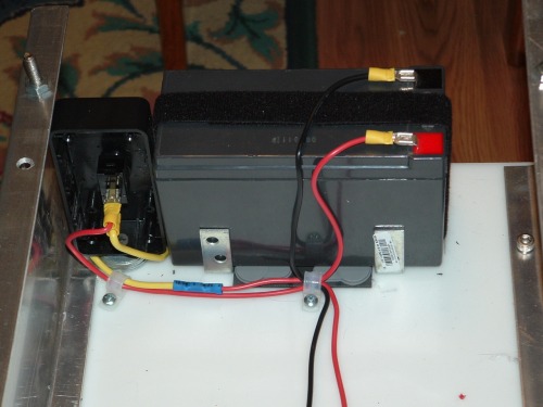
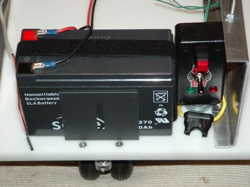
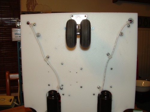
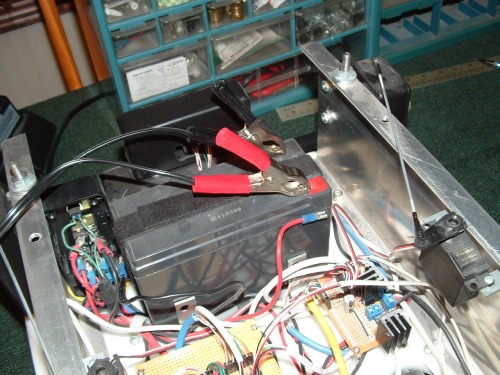
I finalized my battery mount. My first try was too unstable with the battery wanting to move toward the center. I added brackets and rubber feet to secure it. Also I used an old project box that I had bought for a past project and discarded because it was too small. I used it to mount my master on/off switch and I will mount a power LED that I have [if I can find it again]. I wired in a fuse for the robot also.
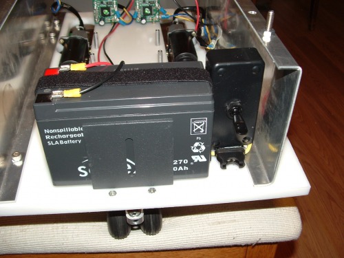
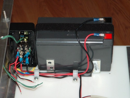
The back side preliminary wiring and the extra battery mounting brackets...
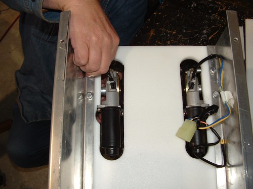
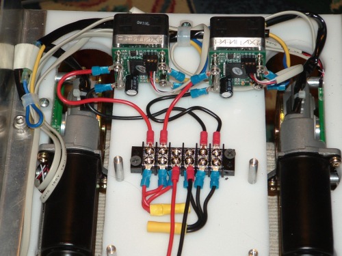
I finally decided on how to mount the HB-25 motor controllers and partially wired them. I also mounted the BOE-Bot BS2 board which is the same size as my Propeller Proto board. I will use either the BOE-Bot board or the Homework Board that came with the wireless kit for the initial motor and motor controller tests before attempting it with the Proto board.
The reason that I will run my initial test with a BS2 board is simple. Parallax has the code available to download for the BS2 but not the Propeller. The BS2 sample code will move the motors forward 350 ticks. Each tick is 1/2 inch of movement so that equates to a little over 14 and 1/2 feet.
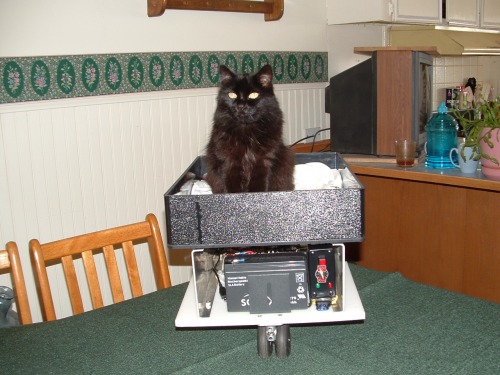
"The Grue" is double checking every thing that I do with the manuals to make sure that I am following all the proper proceedures in the construction...LOL

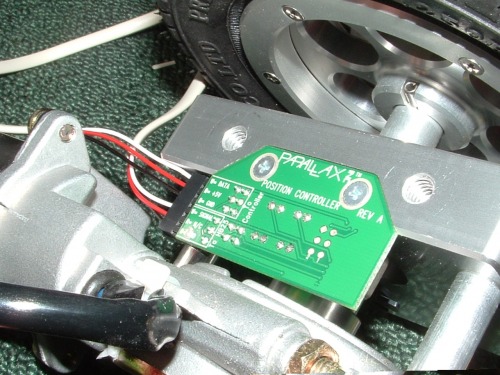
Next I mounted the position controllers on the motor mounts which have built-in microcontrollers and they are daisy-chained so that I only need one pin from my BS2 or Propeller to control up to 4 position controllers and a total of 4 HB-25's [one for each position controller]. That could give me 100 amps of power. TOBI has 2 so I can have 50 amps of power to motors
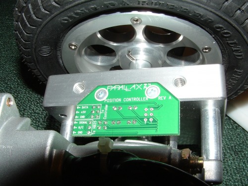
One issue that arose from mounting the Position controllers was of clearance. As seen in the photo, the circuit board is flush with the motor mount BUT the soldered points are not! They are above the mount surface. After bolting it back on the chassis, the wheel was at an angle giving TOBI that sway-back horse look. I purchased washers and used them as spacers above the mount and the angle was true once more.
Each position controller has an output to one HB-25, an input of GND, +5 and the Data from my primary microcontroller. This also has an ouput of GND, +5 and Data to the next position controller in the chain. Each position controller is assigned an address via a set of jumpers. A second issue was clearance again. You have to plug the wires into the position controller before you mount it on the motor mount unless you have really tiny hands [like a childs hands].
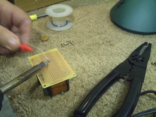
They did not come with cables so I started to make mine from scratch. I also decided on an idiot-proof connector for the position controllers so that I will not accidentally plug something in wrong. My connectors will be keyed so that they can only be connected in properly.
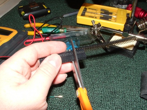
Once I cut the right size, I had to shave off the rough edges.
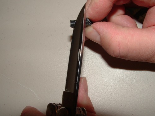
I did the same for the single wide 3 conductor ends [no pics since you get the idea].
I will use an old DSL cable that I found laying around. It has 4 conductors and I only need three [the colors match perfectly]. Unfortunately I need a smaller crimper tool than the ones that I have.
More updates when I get the crimper and work on the wires...
UPDATE 2009.05.17
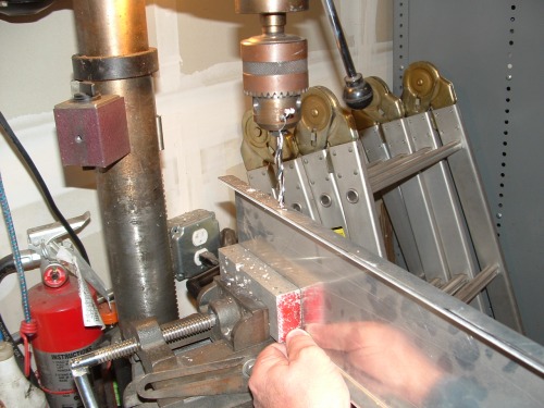
I finished the control wiring for the Position Controllers and HB-25's. I had to buy this small stripper to crimp the ends.

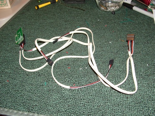
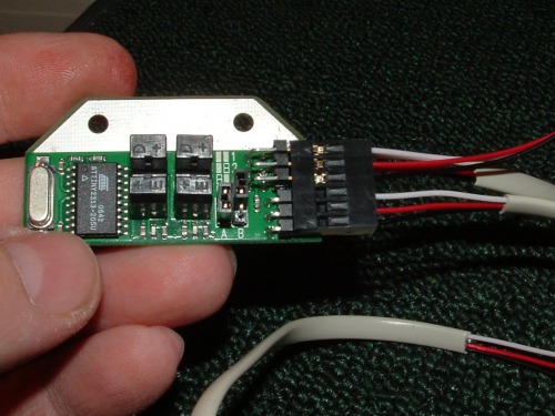
The finished control wiring made from an old DSL cable and my custom ends.
And how it connects to the Position controllers.

The wiring and Position controllers mounted on each motor and mount.

The almost finished wiring. The Power Bus is finished and also the my Control Wiring. What I came to find out later was that I had motor wires reversed but I saw them wired that way in Schematic. Pay close attention to the documentation for the Motor Mount & Wheel Kit with Position Controller as to which wire colors from the motors connects to M1 and M2 on the HB-25's.
I redesigned the front/rear control panel. I changed the switch out, added a momentary switch for resetting the microcontroller and also two LED's for power and error messages.
I have not yet connected the momentary switch or the LED's yet.
Here is the finished wiring for the first roll test using the BS2 controller.


This is the final setup for the first roll test.
As I stated earlier, the first bench test was unsuccessful. One wheel started later than the other, then they moved forward a while and finally they switched from forward to reverse very rapidly. I rememberd the description of the wheels not starting at the same time and found the issue with the correct wiring description in the manual.
After correcting the wiring, my roll test worked perfectly. I played with it in my driveway and once in my dining room for my first video. I'll post the video as soon as I get some daylight shots!
UPDATE: 2009.05.18
Video of a rolling TOBI finally shot and uploaded.
I also tested TOBI at a local scateboard park to see what kind of hills it would climb unloaded. Sorry no video. I decided to show the very first indoor test also.
I ran TOBI up the steepest wheelchair ramp that I could find in town for the video.
At this point TOBI is just running preprogrammed patterns and I am running on an altered version ot the test code for the BS2. I am going to run more tests of the motors with the BS2 and I am toying with the idea of connecting up the wireless link with the two BS2's for more testing until I switch over to the Propeller board. At this point I am undecided but completely enjoying the journey and all of the challenges.
UPDATE: 2009.05.18
Had some issues with the wiring of the motors and HB-25's so I contacted Parallax:
My Post
I recently purchased the Motor Mount & Wheel Kit with Position Controller kit to creat my robot and have had some strange behavior with the programming. I ran my first roll test with a BOE-Bot board and the BS2 test code from the web site. It worked fine until I decided to try reversing the opposite position controller in the software. Then the robot ran away at a faster rate of speed and when it got to about the 400-500th position the wheels then switched to a high speed oscillation until I powered off the HB-25's. I wanted my forward to be in the opposite direction and thus the reversal of the position controller [or so I thought]
So the next thing that I tried was reversing the wires on HB-25's since I saw that in one other post here in the forums that it did not really matter. Still the issue occurs when setting one in reverse. Here is the strange thing: when you reverse the wiring on the HB-25's you have to reverse in the software the other position controller to make it work flawlessly. Again forward equals wheels first and caster last which is what I don't want now for testing purposes.
Why is it so finicky about the correct wiring and the exact controller that needs to be reversed? Currently it is wired like it says in the documentation and the position controller in the test code is the one that I have reversed. I have to issue a negative number to get it to run caster first.
Parallax's Reply
The reason that correct wiring is so important for the motors is that the motor must go the correct direction when the Position Controller tells the HB-25's to go "forward" or "backward". The Position Controller sends signals to the HB-25 in order to drive the motor to a certain location. If the motor is reversed, then the more the Position Controller tells the HB-25 to drive TO the location, the more the motor actually drives AWAY from the location.
The reason the "Sensor Orientation" of each Position Controller is important is because that is what determines how motion is interpreted from the optical switches. This is from the data sheet:
"The default definition for positive direction of travel is counter-clockwise rotation when
observing the wheel from the outside (screw side of the Position Controller board). After
receiving the SREV command, a Position Controller will interpret positive direction of travel
as clockwise rotation from the same viewpoint."
So if the motors are connected correctly, but the Position Controller isn't "oriented" correctly, then the Position Controller interprets the direction of motion as opposite what it should be, and then consequentially tells the HB-25's to drive in the wrong direction.
Incorrect wiring OR incorrect sensor orientation will both cause an undesirable state of operation. However, this is one situation where two wrongs CAN make a right. Let me elaborate. As you pointed out, normally the default setup is that "forward" is in the direction of the motors, and "backward" is in the direction of the caster wheel. This is what the demo code and default setup in the data sheet describe. Literally, the only difference between forward and backward is just a negative sign. However, if you really don't want to deal with a negative sign... then (step 1) switch the polarity of BOTH motors to be opposite what is described in the data sheet, (step 2) send the SREV (sensor orientation reversed) command to the OTHER Position Controller and don't send it to the default one. Essentially, it is a double negative for each wheel: the motor wire polarity is backward, but the sensor orientation is backward too so both incorrect directions cancel out the error. However, the result is that "forward" is now forever defined as the direction of the caster wheel, and "backward" is in the direction of the motors. To change it back again, you must swap both motors' wires, and again initialize the opposite device to be reversed.
Hopefully this helps, and gets you "up and rolling" so to speak.
-Kevin
My Reply
Thank you.
The double negative makes sense to me now but I did not see that in my troubleshooting. I think my confusion came from not knowing which position controller on which wheel was suppose to be 0 and 1 respectively. I must have missed that in the docs. Anyway, with your help I got it to run caster first with positive numbers.
Thanks
---------
I deal with a lot of tech support people in my job and Parallax just blows away all of them. They don't push product on you and they don't put the blame on a non-Parallax product like other vendors. They are very helpful interfacing other devices with their products.
Final Configuration:
I am running my robot with the caster first. With that end as the front, both of my HB-25's are wired with M1 to Blue and M2 to Yellow. The position controllers are set with ID 1 on the left and ID 2 on the right. In the code ID 2 [Right] is reversed.
UPDATE 2009.05.21
Developement Decision: I have decided to further develope using the canabilized BOE-Bot and BS2 until I have mastered the motor controllers command set before moving onto the Propeller. Also my ulterior motive is to get the Wireless interface running ASAP for some fun..I mean some extensive mobility tests. LOL!
I keep thinking about posting a schematic of my current layout but I keep putting it off since I keep adding things.
UPDATE 2009.05.25
I assembled the Wireless Control for Robotics kit and got good readings from the accelerometer.
I added the Wireless reciever to the BOE-Bot powered TOBI and recieved great readings from the accelerometer via the wireless link.
The next thing that I need to do is to translate the readings from the accelerometer into movement commands for the position controllers.
UPDATE: 2009.05.29
The accelerometer kicks out a number between 1775 and 3125 for each axis [x & y] according to the tutorial PDF from Parallax. My readings were from about 1800 to 3170 so I was close. The wireless kit just uses the BS2 to read the raw data and transmit it to the BOE-Bot. All of the conversion and navigation decisions are done on the BOE-Bot end. Since I will replace the BS2's on both ends with the multi-core Propeller chip, I wanted to utilize the processor power in the remote to lighten the load on TOBI.
First I converted the raw data by subtracting 1775 which gave me a range of about 90-1380 with the center around 750. This was more resolution then I needed. I decided that I wanted a center and two speeds for directions. I divided my number by 100 and that trimmed it down to 1-13 for the processed readings from the accelerometer. Then I simplified it to a 1 - 5 directional scale with 3 as center point [STOP].
Directional Translation: 1 | 2 | 3 | 4 | 5
Accelerometer Readings: 1-2-3 | 4-5 | 6-7-8 | 9-10 | 11-12-13
I transmitted my Directional Translations to TOBI for directional interpretation. After I first fired it up, TOBI started ramming furnature until I steadied the transmitter. I decided to at a toggle switch to the transmitter. When the toggle switch drives one of the BS2 pins LOW, the BS2 turns on an LED and transmitts the directional instructions. When the toggle is OFF and the pin is HIGH, the remote will only transmit 3's for both x and y. That stopped all of the erratic behavior when I first turned on the remote or picked it up from a table surface.
I also decided to add 3 maximum speed limits. I want an "Office" speed [about 18], a "Outdoor" speed [about the default of 36] and a "JackRabbit" setting for scooting across a busy street quickly. All speeds except the "JackRabbit" will share the same common navigation settings i.e. slow forward/backward at half of the max speed, fast forward/backward at the max speed, veer left/right and rotate on left/right wheel [movement 0] for a hard turn.
"JackRabbit" will be just a high speed forward with no left or right turning and no reverse. Its purpose is entirely to shoot forward to cross the street before getting squashed by a vehicle.
The programming I am currently running is even simpler. It just has forward, reverse, left and right [all at speed 18 "Office" speed]. The third video of the Wireless Test is using this code.
My next step is probably more testing on speed control and fine tuning. Then I will be ready to replace the BOE-Bot BS2 board in TOBI with the Propeller board and start development in SPIN for TOBI. After I get mobility from the current BS2 remote control, I will trade it out for the PropStick based remote control. That will conclude the TOBI - 1 phase and I can then start adding sensors to start the TOBI - 2 phase.
More to come. I will post my current code for all to see and if someone expresses interest, I will post a schematic of the remote and TOBI as they currently are wired.
Tobi_TestTiltToMovement2.4.bs2_.txt
TOBI_TestTiltTransmitter_Directions4.bs2_.txt
UPDATE: 2009.06.14
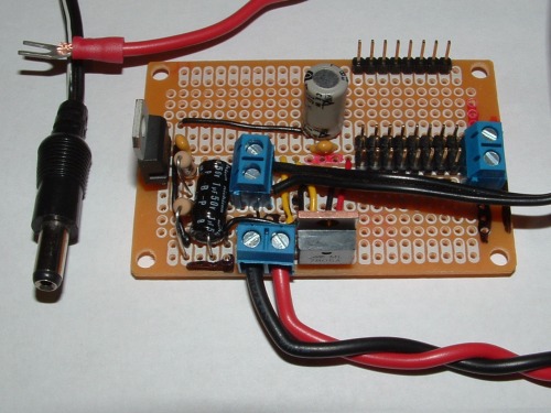
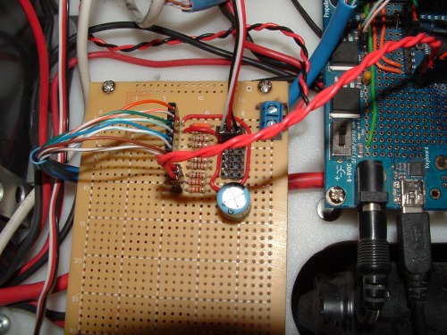
In the furtherance of moving to the Propeller Microcontroller I have built a dual voltage regulater board with with one output at 8.25V for the Propeller boards I have and the other at 5V for peripherals with a three pin header for GND/+5V/Signal. Each signal pin will have a resistor to drop the voltage down the 3.3V that the Propeller runs on. I used the LM317 to get my 8.25V and this might sound like a weird voltage to use, but I needed my voltage to be between 7V to 9V for all of my BS2 and Propeller boards. I found a cool page on that voltage regulator:
http://www.reuk.co.uk/print.php?article=LM317-Voltage-Calculator.htm
I decided to use fixed resistors instead of the variable resistor in the schematic and went to Radio Shack to see what resistors they had in stock.

My input is from my main power distribution strip. The microcontroller power [8.25V] is the in the center [Black cord]. The black three pin header mounted in the lower center provides my 5V power and I mounted a header on the lower right edge for connecting to the microcontroller board. Resistors will be added in between the two to drop the voltage or a strait connection for output only in some cases.
I have to add heatsinks to the two regulators and it will be ready for operation. It has passed all my tests and works. After that I have to mount the resistors on the interface and make new cables for most of my current peripherals. While I was at Radio Shack I found that they sold a Parallax Ping))) and other sensors, so I picked up the ping. I am hoping to get TOBI running under Propeller power before the Propeller Expo in 2 weeks. I don't think that I'll make it, but I am going to try.
UPDATE: 2009.06.18
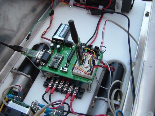
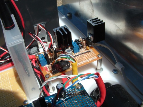
Got heatsinks on the voltage regulators and added the 1K resistors to my 5V to 3.3V interface for the Propeller board.


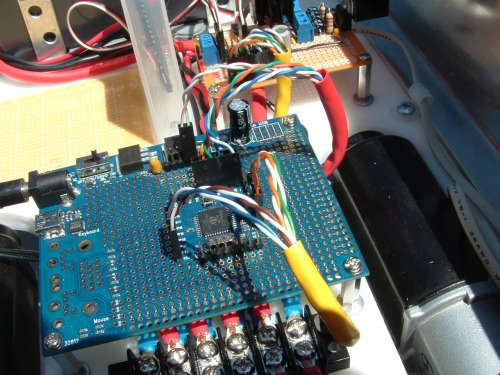
I installed the new board in TOBI and traded out the Basic Stamp board with the Propeller Proto board. The first power up test was successful.
As you can see, the motor controller cable that I made plugs in nicely to the new board. Now I have to add risers to my Propeller Proto board and make cables. Two cables to start with. One with 8 conductors for my new board and a second that connects to the LED's and resect switch on the front control/status pannel. I also moved the battery back so that I could mount sensors like the PING))) or my LCD disply up front.
Just a little more soldering and wiring will bring me to the first Propeller based roll test.
UPDATE 2009.06.22
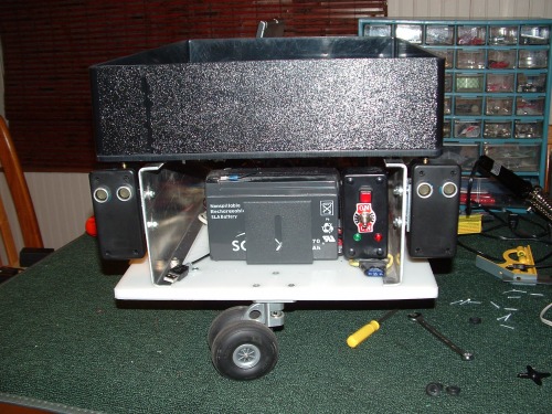
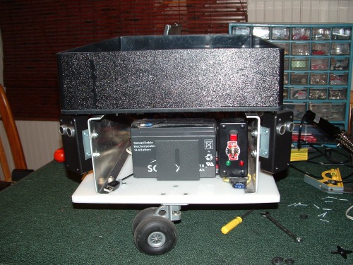
The first change is the new battery placement so that I can mount sensors up front and possibly my LCD display when I get the the TOBI 2 phase.
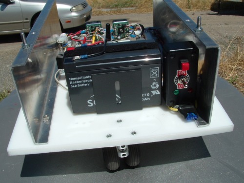
In the picture you can see the RESET/FUNCTION Switch at the top that is a momentary switch. The POWER switch and below that is two LED's [Green and Red]. The POWER switch is a three position with center as off. In the center, both leads of the battery are disconnected from all of the elctronics. The UP posision is ON and powers the robot. The DOWN postion connects the battery to my charging plug on the back of the robot.
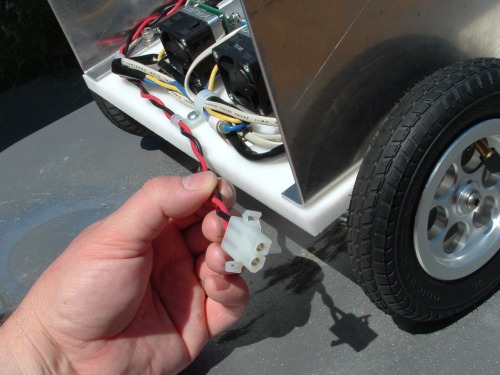
My charger from Harbor Frieght had aligator clips and I cut them off to add these couplers. I put a coupler on the alligator clips also so that I could charge any other battery.
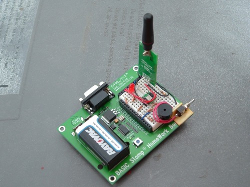
The next thing that I did was to add headers to my Propeller Proto Board so that I can easily plug in my modular based systems like my 5V to 3.3V interface board.
To test the Proto Board I connected it to the LED array on my PPDB and ran a test pattern program.
After this successful test I had wires to create. I got some yellow Cat-5 network cable and started on the 8 connector for my 5V to 3.3V interface board.
Cat-5 was perfect for my 8 connection interface and I have loads of it. I have two things plugged in. The first position [Orange] is the Position Controllers for the Motor Mount Kit. The other one on position 5 [Blue] is my wireless reciever. There is a method to my madness.
I decided at the last minute to split the workload. Oranges and Greens are pins 0-3, Blues and Browns are pins 20-23. The Propeller can handle 30mA per pin max but each group of eight can only have a max of 100mA. So wanted to maximize my options. Once that was completed I started work on another wire made out of a red colored Cat-5 Cross-Over cable. This cable connects to my front pannel LED's and my momentary switch. I used the Normal-Low-Push-2-High circuit in the PE Kit documentation. My LED's and switch are connected to pins 8-10. I put my connector on the Propeller side and soldered on the front panel side and used black tape for shielding.

I found this really nice protptype board at Radio Shack last Wednesday and thought that it would be great for my ADC circuits to convert the Sharp IR Analog signals to a digital distance reading when I get to the TOBI 2 stage.
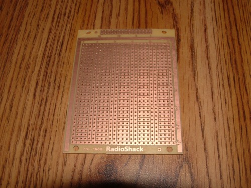
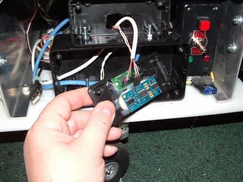
I predrilled holes for it and set it aside for later. I thought that I was done when [like an auto machanic] I found left over parts. In this case I forgot to install my wireless reciever. My wife and I spent considerable time scrounging for a solution to mount the wireless reciever inside TOBI that was just the right size. My wife found an old cover from a DDS backup tape that was just the right size and made of type of plastic that would resist shattering.
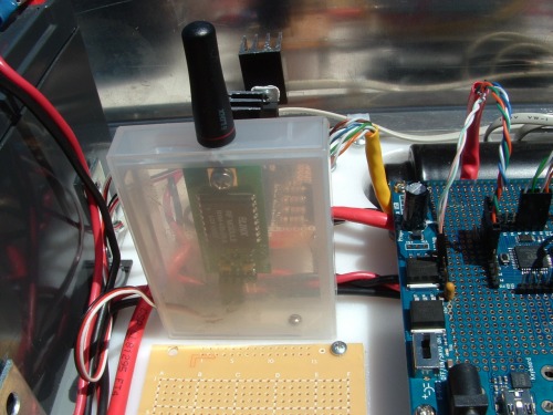
The antenna is removed from the reciever by one screw. I drilled a hole and reassembled the reciever inside the box. The box opens toward the camera and I decided to use a premade cable for this because of time. I may replace this in the future with one that I make.
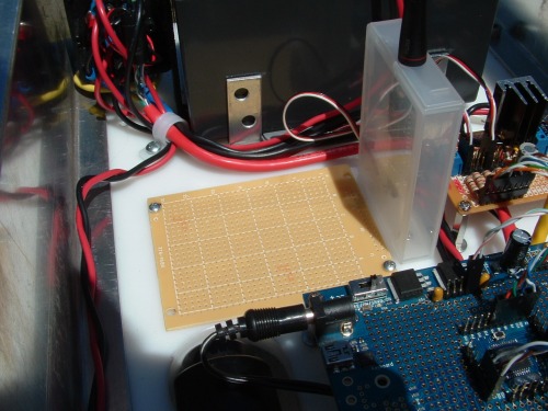
With my predrilled holes for the expansion board you can see that TOBI is running out of space on his deck. Hopefully this board will take care of all of my ADC and I2C needs for TOBI 2-5 models.
This finishes the hardware and wiring for the TOBI 1 robot base. I could have done more if I had the full weekend to work. I am now back to square one with this new platform. The only thing is that I know that all of the parts are tested and functioned with the BS2 board.
Next Steps:
1. Code the robot for the first roll test under Propeller power.
2. Code the robot to read the accelerometer on the BS2 Homework Board wirelessly [previously used above] and move accordingly.
3. Build and code the new [permanent] wireless remote control using the PropStick, accelerometer and RF transmitter.
It doesn't look like I will have a working TOBI for the "Propeller Expo" on this upcomming weekend [6/27-6/28] but I still may take it since there are booths set up for attendee's to show off and/or work on their robot projects.
As for "The Grue", she is impatient for her new ride...LOL
UPDATE 2009.06.25
TOBI has now had a successful roll test with the Propeller Microcontroller. Code could not be posted because of limitations on the types of files allowed on this site. So I printed the code directly from the Propeller tool into a PDF file. It looks almost as good as the Propeller Tool. Check it out [Propeller MPC_Roll_Test.pdf].
Now onto reading the accelerometer from the wireless link...
UPDATE 2009.07.16
I started coding and stopped thinking "wait a minute, I need to know how I want TOBI to run and what decisions he needs to make". So I stopped coding and opened Visio and started to "map out" his logical flow. So I just uploaded my first page of his logic processes. Other than that, life has stepped in the way of my robotic developement right now.
UPDATE 2009.07.18
I did more work on his flow chart of decisions. Plus I was working on the future TOBI 2 designs for a sensor array and the logic for the "Main Mission". I still have the sensor logic to create but I am getting close to my first prototype. I still have the sensor array in my head but I will go to Redding soon and make it a reality.
Next Steps:
Finish the map of the sensor logic as I see it now.
Hard wire the accelerometer to TOBI and get readings from it.
Convert those readings to movement so he moves by a wired connection
Replace the wire with the wireless transmitter/reciever set up
Sweep all bugs in the system
Build the final wireless remote with the PropStick and connect it to TOBI
Bug sweep the system
------------ At this point TOBI 1 would be done
Buy 2 more PING))'s and one Sharp GP2D12 IR Sensor
Construct the Sensor swivel mounts and mount the all front sensors.
------------ From here on it gets a little hazy -----------------
Construct the ADC circuits for the SHARP IR sensors
Test the system in the real world, bug sweep and make additions/modifications as needed.
UPDATE 2009.07.25
This week I retrofitted my BS2 powered Wireless Control for Robotics to send the raw data from the accererometer and I hard wired it to my Propeller PPDB [removing the wireless transmitter/recievers from the equation] in order to develope the communication code between the remote controller and TOBI. Although I found that it is a simple matter to create a serial output to a device using the "SimpleSerial", "FullDuplexSerial" or "FullDuplexSeriaPlus" objects, I am wrestling with how to create a serial input on the Propeller. I haven't found any good examples of this [to date] that make any sense to me. So far, all I am getting is garbage BUT I am getting something from the BS2.
The BS2 BOE-Bot board that I used in my roll tests and wireless control videos uses a command called SERIN to recieve the data from the transmitter. The transmitter BS2 uses a SEROUT command to send a start character followed by the two variables. I found an object on the OBEX called "BS2_Functions" that has four versions of SERIN commands for me to analyze and play with. If all else fails, I'll try the Parallax Forums.
As a side note: I have decided to wait on entering TOBI in the "2009 Propeller Design Contest". I don't need the pressure right now in my life. But if I get to the TOBI 2-3 level before the deadlines, I will enter him in the contest.
UPDATE 2009.10.01
It has been some time since the last time I worked on TOBI and updated this page. After several trials I just cannot get the Motor Position Controllers to act the way I want TOBI to act. Here is what I found:
The MPC's have to be told how many 1/2" increments to move forward, which is not too bad since you can tell it a long distance and then send a 0 to have it stop. I just want to have it move forward and not care about distance.
They have a cool auto ramp rate so it speeds up to full speed from a stop and slows down to halt at the prescribed distance. The bigest limitation on this is that if you have too short a distance programmed, TOBI will start to speed up and then slow down to a stop, with never reaching his full speed in between.
Speed is an issue too. If you change the max speed in travel to a faster setting, TOBI will increase his speed according to the automatic ramp rate. But if you decrease the speed, the motor instantly cuts the current speed down to that speed. This makes it very hard change the speed with a smooth ramp rate because you have to send your own ramp code in order to have a nice decrease in speed. Also, to steer by changing the speed of one wheel is a royal pain with the distance setting usually changing the robots' heading when he eventually stops or it makes it turn in unexpected ways.
So I scrapped the idea, finally, of using the MPC's and wired directly to the HB-25's. Now I just send standard servo pulses to control the motors. Lots easier. I did run into one issue that held me up for over a month. I could get my servo pulse code to control the HB-25's from my Developement Board but not from the Proto Board that is the controller in TOBI. I wasted lots of time until I figured out that it is some sort of digital interference on the power bus that makes the HB-25's think that the pulses are incorrect [and hence ignored]. I resolved the issue temporarily by powering my logic circuits on a separate battery and the issue went away. I hope my hair grows back...LOL
The up-side of this aggravation is that I finally broke down and made schematics of TOBI. The first page is both actual and future configuration combined. The second page is completed and there will be a third page for the Sensor Array and a fourth for the wireless remote control.
I purchased two more PING)))'s so I am just missing one Sharp IR sensor. I am going to Redding Saturday to work on filtering out the digital interference so that I only need one battery. Also I will work on the PING))) and Thermal Sensor mounts. I still have to work on my wireless remote control but that will come later, not sooner, and I am intrigued by some new 3.3 volt trancievers and a 3-axis accellerometer that just came out that would make my remote even smaller in size.
Anyway I am posting the Schematics that I have so far. I have fallen in love with that "ExpressSCH" for making schematics!
UPDATE 2009.10.19
I ran into another perplexing problem with the Propeller Proto board and the HB-25's. When I went to Redding we worked on the problem by making some filters to filter out the digital interference

The circuit was simple, just a coil and several capacitors.

We installed the temporary circuit in several different ways and had the same results as if it was never installed. We discovered that it was simply a timing issue not interference. For some reason the Propeller Proto Board and the HB-25's cannot be powered on at the same time by the main switch. If either is turned on first, followed by the other one, then the robot always moves according to the pulses sent. But if they are powered on at the same time with the master switch, 19 times out of 20, it will not move, no matter how many pulses you send. So I took a cue from another builder and will power on the HB-25's using a relay controled by a pin on the Propeller. See my new schematics: TOBI_Schematics_Part_1_2009.10.19
My brother and I also went on a shopping spree. We got some project boxes to mount my PING)))'s, my LCD display and the TPA81 Thermal array sensor on the front of TOBI. We also picked up some molding from an RV shop to make bumpers for the front and back of the robot. My brother also talked me into the idea of getting another servo, so that the left and right IR/PING)))'s could move independantly. It would also negate the need to have a moving bar in the front of the robot that links the two together.
So I have decided on two moving sensor arrays [Left and Right] that consist of 1 PING))), 1 Sharp GP2D12 at a 45 degree down angle and a servo to sweep it 90 degrees. Also a Center sensor array of 1 PING))) and the TP81 Thermal Sensor aimed slightly upward. We spent so much time hunting for parts that not a whole lot of work was completed. I also plan on having some Sharp IR's on the back of TOBI for when I reverse. I don't want it to run off a cliff, you see.
I also uploaded my code for the testing of my HB25's. See: TestTobiHB25_Sequential_3.txt
UPDATE 2009.12.06
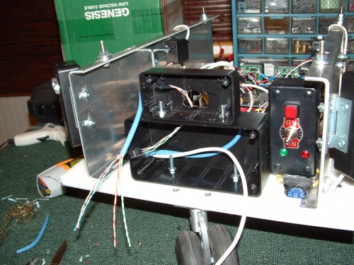
So this a major addition to TOBI that I did over the past Holiday and the weeks afterward. Here is what TOBI looked like before the work was done:
So on to the upgrades!
The issue mentioned above about the HB25's was solved but the installation of a relay. I had to move my power bus in the process to make room for it.
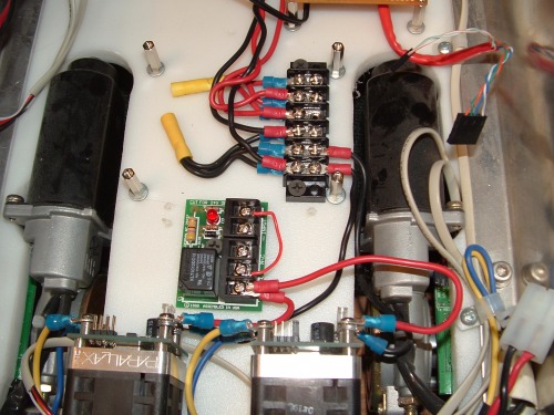
Here it is installed and running perfectly.

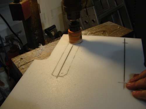
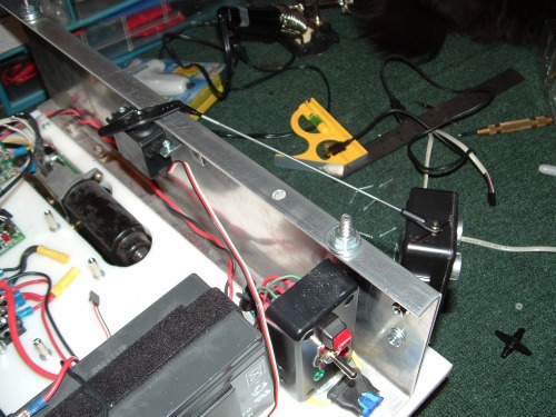
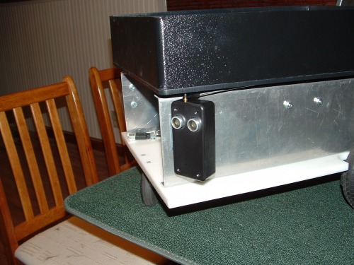
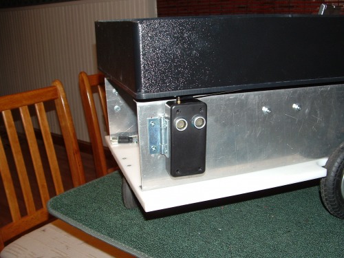
Work has progress in the above mentioned sensor array on the front of TOBI starting with the side mounted PING)))'s
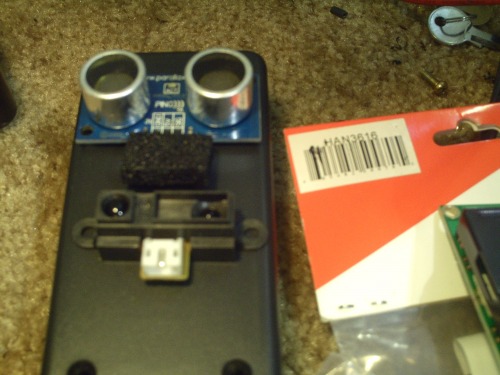
We lineded them up so the PING))) is at the top and IR will be below it looking down at 45 degrees for edge detection.

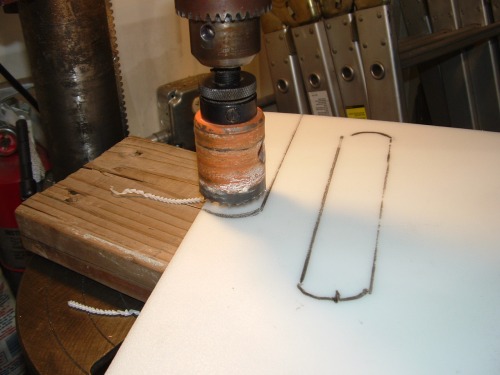
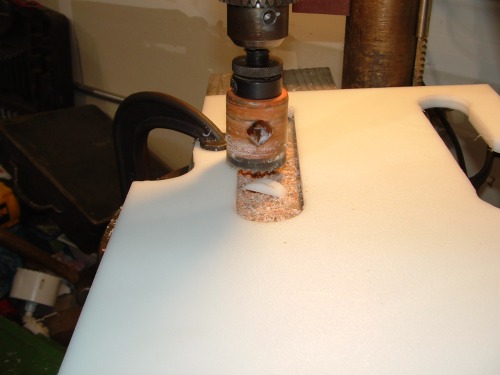
We drilled pilot holes first.

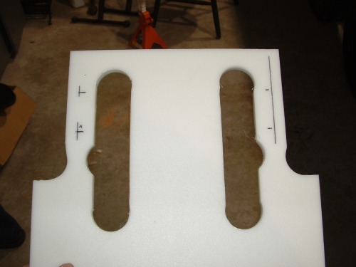
Then with a special bit we enlarged the holes to fit the PING)))'s

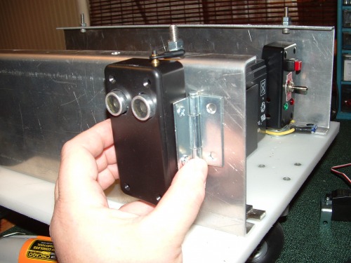
They fit the project boxes that I bought at Radio Shack rather well. Next I mounted the hinges on the boxes and then fastened them to TOBI.
I went to a hobbie shop and bought some fasteners for the top of these boxes to attach them to servo arms. I also picked up a selection of servo arms and rods.

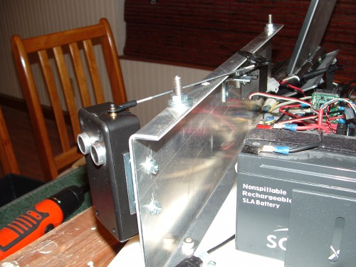
After mounting both boxes I had to fashion mounts to mount the two servo's for each side.
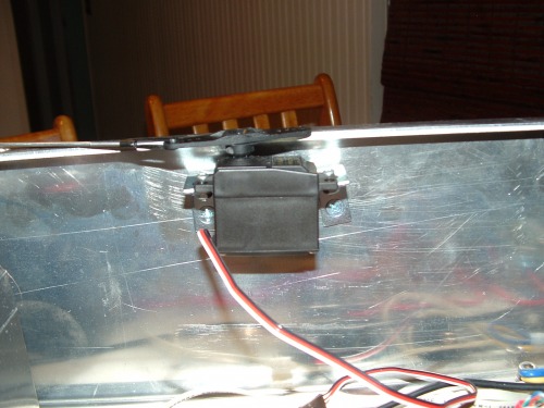
Since the rods move between the metal frame and the plastic bed, I had to add washers under the nuts to raise the bed higher as seen in this picture.
The length of the servo horn and the placement of the connection on the sensor box from the center point on the hinge had to be exactly the same.
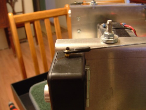

I will have the center position keep the sensor boxes at a 45 degree angle. I will have to carefully program the servos to only move a maximum of 45 degrees from the center position. This could give me three important readings:
Front

Corners
Sides
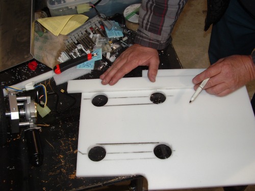
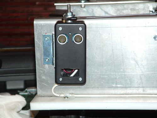
The next thing I installed was the center PING))) and the TPA81 Thermal Sensor array. I lined it up and drilled the holes but this time horizontally on the Radio Shack box since I wanted to install it on top of a larger box that would house my Serial LCD screen.
This time I wanted the PING)) to be flush mount in the box and the TPA81 to stick out. Also I wanted the TPA81 to look up at 30-45 degree angle. I thought long and hard about this and finally came up with a solution. ShapeLock plastic. I warmed up some ShapeLock and made an angle mount for the TPA81 and hot glued it to the box. I thought about hot gluing the PING))) but I could not bring my self to do it. Instead I warmed up some more ShapeLock plastic and rolled it into a long peace and wrapped it in a figure 8 around the PING))) and let it set on hard table. Once it was set I centered it on the holes that I drilled in the box and hot glued it into place.

I had to bend the leads on the PING))) [there goes the warranty] but it fits nice and snug in the ShapeLock.
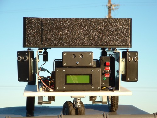
Here you can see the finished array component monted on the LCD display.

As you can see, the hardware is mounted now and TOBI looks pretty cool.
Now I have to wire it all up and center the servo's. I got a new Dremal tool and tried it out on the box for the LCD. I fairly butchered it until I got the right bit and the right technique down. I was going to mount bumpers at the same time but the metal frame and bumper material I bought for mounting on moter homes was not thick enough. I was afraid that the metal would hit and scratch a client's wall, which would get me in trouble with the client, not to mention my employer. I asked my brother Clark to go to a Trim-Line shop to pick up some of the narrow metal and bumper material that they install on cars.
At this point I will not install the Sharp IR sensors because I have wire up the ADC circuit for interfacing to the Propeller Chip so TOBI will not be able to do edge detection. I have a lot of wiring and planning left to complete just the hardware aspect of this phase of development, not to mention the programming phase.
More to come...
UPDATE 2009.12.31
Well I was able to test my three PING)))'s with the Propeller Debugger software.
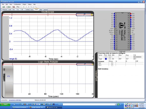
I found that only one is giving odd readings. It was the center one above the TPA81. I widened the holes and did not push it all the way into the ShapeLock mold. Only then did it seem to give better readings. That is what I get for buying parts at Radio Shack instead of at Parallax.
UPDATED: 2010.01.04
Today I found that two other sites featured my robot: Hacked Gadgets and Hack A Day.
Anyway, the New Years Holiday saw a lot of work on TOBI. Not only did I get to play with my new debugger software [pictured in the previous post] but I got to finish the wiring on my PING))) sensors and test all the mounted PING)))'s and the LCD.
First I ran the wires to the side sensor arrays.

Here is the fully wired PING))) in one of the sensor arrays with cut out hole for the Sharp IR to be added later.
Here is the wiring for the Center PING))) and the LCD below it.
This is the Center PING))) and the Thermal Sensor which uses four wires [+5V, Gnd and 2 wires for the I2C connection]
Also I tested and adjusted the servo arms so that the arrays move 90 degrees. I updated my schematics to reflect the current wiring and started on a programming template for TOBI in Propeller Spin language. I was hoping to shoot video today out in the sun but the weather prevented it. So that will be a future update. Except for the thermal sensor I2C connections, TOBI is ready for programming and testing his autonomous features.
UPDATED: 2010.01.10
Well the Sun did not come out all week but it was bright enough to shoot some video today. So I shot video of the test of TOBI's new sensor hardware. In this test I tested the wiring and function of the front mounted LCD and the Servo's that sweep the side PING))) sensors 90 degrees. What I did not film was that I retested the PING)))'s after mounting in the movable housings. To complete wiring on TOBI 3 I need to finish the I2C interface on the Proto Board and conned the Thermal Sensor to it. Once the hardware is done then I need to work on the programming which is my weakness.
I believe that I will have to put TOBI building aside and concentrate on learning the SPIN language. There is tons of free documentation like the Education Kit documentation and the Propeller Manual V1.1 that I can learn from and videos on the Parallax site along with many free Object Modules on the OBEX and Parallax Forums as examples and for tech quenstions answered.
Also there are two up comming books on the Propeller: Programming the Propeller with Spin: A Beginner's Guide to Parallel Processing (Paperback) and this book: Programming and Customizing the Multicore Propeller Microcontroller (Paperback) that I want to pick up for reference. I just need to make sure that my TOBI Schematics are up to date so that I can pick up where I left off after my Spin training is over.
UPDATE: 2010.04.07
I have been working on learning SPIN from the Propeller Education Kit documentation and I am starting on the last chapter, chapter 6 when I just needed a break to build something. I bought the parts and have been working for 2 and a half to 3 weeks on the project. I was working on the remote control for TOBI so that I can take him out in the real world with a wireless safty net. I documented the entire remote control build in the "Something Else" section and called it RoBo Remote instead of TOBI remote because I can use this same programmable platform to control 8 different XBee connected robots/devices.
Now that I have some building done and have something physical to hold and see, I feel ready to hit the books again and finish the traning manual. After I am done, I will install the XBee device on TOBI and finish the I2C connection for the Thermal Array Sensor.
UPDATE: 2010.04.23
Ok, so I did not go back and hit the books. Instead I worked on the RoBo Remote and making TOBI run these last 2 weeks. I took it in steps and even made TOBI move smoother by using a ramp rate. I added diagnostic data to be displayed on TOBI's front mounted LCD. I spent some time working out some kinks with the LCD. It has three baud rates and the fastest one prints just garbage. 2400 baud is just too slow and I got 9600 to work fine but despite setting pauses it still ignored about the first 3 to 4 commands sent to it. So I just sent them again and then it works fine after that. I don't have a video camera to shoot video but I have a Gum Stick Spy Cam/DVR so I just shot some video with it. It does not have a viewfinder or display so I had to shoot it and then look at. Pardon the poor lighting. I plan to work on TOBI this weekend and try to get the sensors integrated into the programming. I also attached the current software that TOBI is programmed with for the video. Check the RoBo Remote site for the software loaded on it for this video.
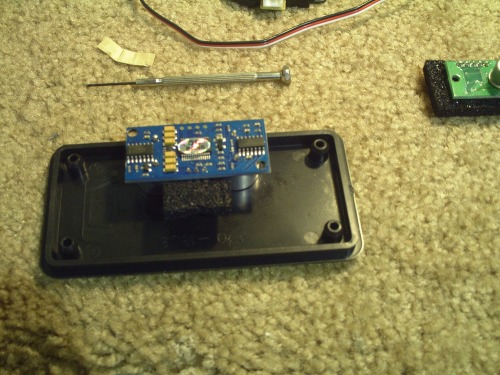
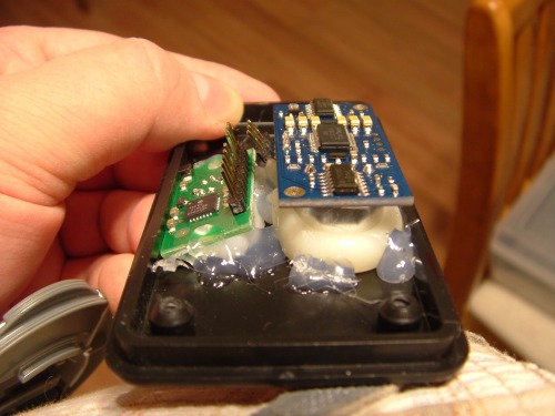
I installed the XBee Carrier board on my Propeller Proto board and connected the ground, power, RX and TX pins.
Next I mounted the XBee transmitter on the board.
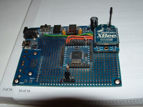
Finally I installed it in TOBI

UPDATE: 2010.05.09
I updated my RoBo remote to work with multiple robots. It now sends just X and Y with some other options including a new Reverse option so that I can run TOBI wheels first or caster first. I have some little wiring left to get the Thermal Array connected and then all the sensors will be ready for programming. I ran into issues with how I was sending my remote control pulses when I tried to add the sensors. That is when I decided to rewrite my RoBo remote code. Everything is functioning as it was before with the addition of the new Reverse option. TOBI is now computing his own pusle codes to send to the motor controllers. More to come...
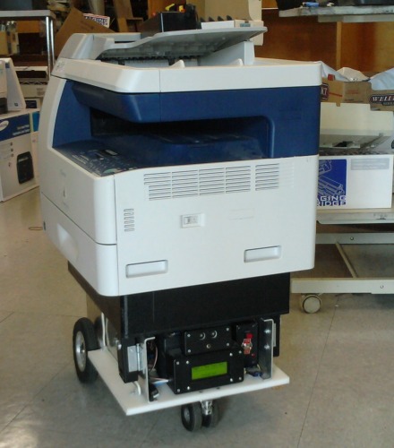
UPDATE: 2010.05.24
I worked some more on TOBI's Sensor Array and had to test him on moving loads. I have moved computers, monitors and, as seen by the latest video I posted, printers. I have been working TOBI for a little over a year and have made a lot of progress. I am looking forward to the Parallax event on 6/27/10 at the Parallax offices.
UPDATE: 2010.05.26
ROAD BLOCK!!!
I had my scanning PING))) routine running for the last video of TOBI moving the Printer/Scanner/Copier machine but they were just scanning each of the 3 positions and putting the results into 7 variables. TOBI was not actually doing anything with the variables at the time. I just recently wrote an object avoidance method to use the variables and overide the RC commands when needed.
It didn't work. I found that TOBI kept running into things unless I drove him VARY VARY slowly. I rewrote the code to be as fast a possible but found that the servo is just too slow. I am thinking that I will have to go back to my origonal design with more PING)))'s for every angle and remove the servo sweeping hardware. It is only 5 weeks now to the Parallax Propeller Expo and there is probably not enough time to re-engineer my PING))) setup.
My current workaround is to set the PING))) array at 45 degrees and use just 3 variables. There is a lot of dead space and I would like to add 2 more PING)))'s to be permanently mounted to face forward for more coverage. I have one cog just for moving the servo's and reading the PING)))'s into variables. I have considered moving the object avoidance method into that cog to speed up process. Right now I need to buy at least 2 more PING)))'s and make mounts for them. I hope that I have enough Polymorph for the project. I also have to make another 5V-to-3.3V interface board to plug them into the Propeller. Also while I am about it, I will have to wire the I2C interface for the Thermal Sensor Array. So I have a lot more physical building before the Expo.
Fortunately my programming is a solid base to work from and would be just fine even if I did not get everything done that I want before the Expo.
UPDATE: 2010.07.04
Last weekend was the "Unofficial Propeller Expo West" and I did make most of the deadlines that I set for myself. First, I had a bug in TOBI that was driving me crazy. For some reason he would stop moving forward and only move in reverse. This was an intermitant bug that came and went. I added more diagnostics to the LCD display, but it usally happened when I was using him at work and had no time to figure it out. I programmed a "Reverse" mode into the RoBo Remote to run TOBI "wheels first" and when this bug appeares, the Reverse mode would work perfectly. I could drive the robot both forward and backward in Reverse mode but only backward in the normal mode. It drove me crazy because it always happened when I did not have time to diagnose the issue and TOBI worked fine when I did have the time. It finally happened at a time that I could dig into the issue.I found that every time I sent forward pulses, TOBI would only see a -3 instead of a positive 1 to 14. it took a while but I tracked it down to my object avoidance routine. The Center PING))) was thinking that it say something that was not there and sent the command to backup TOBI. I traced it down to how I had the PING))) mounted. My brother had thought that it would look cooler if the sensor was flush with the inside of the case. It turns out that the PING))) was sensing the lip of plastic on the case. I used my Dreamel to enlarge the holes and the bug has not appeared again.
Second, I bought 2 more PING)))'s at Radio Shack since that was the only place I could find them on short notice. I used my ShapeLock [Polymorph] to mount them at 45 degree angles [well mostly 45]


Because of space considerations I had to mount them flat to the cutting board material and drill holes into the cutting board to run the wires for the sensors. I ran the wires under TOBI and back to holes for the motors.
I also cleaned up my main power distribution strip

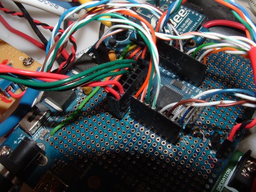
Next came the project of making another 5V to 3.3V interface board with and extra bonus on it.

The extra bonus is the I2C connection that is seen in the top 2 rows and the 2 bottom rows with the orange wires connecting them. This is the 3.3V pullup circuit for the Devantech TPA81 Thermo Array Sensor.
I added a capacitor and wired up another Blue Cat5 to plug into my Propeller board. Also 2 red wires to connect the 3.3V pullup resistors on the board.

So my decided course of action was to use the new PING)))'s and just swing the old one's forward to give me more front coverage. While working on my object avoidance routine, I smashed TOBI into several walls and pieces of furnature [to my wife's dismay]. I damaged my Sensor Array a few times in the process and had to repair it. During this time I thought that I should probably put a bumper on TOBI. I had wanted to create one out of Polymorph plastic with sensors on it to detect collision, but that was financially beyond me now. I was at Home Depot looking for screws to mount my new interface board in the stand-offs from Radio Shack when I stumbled on material for a bumper. At this point I had just thought that I would settle for a soft material for a static bumper to protect the Sensor Array from damage. I found some soft irrigation tubing. I had an epiphany as to how to make it AND with sensors!
I drilled out a large hole on one side of the irrigation tubing and a smaller one on the other side. Then I had some flat metal connectors that I bent 90 degrees and I had some springs from my first failed attemts at making a bumper. All of this magically fit together as if I had bought everything made to fit.
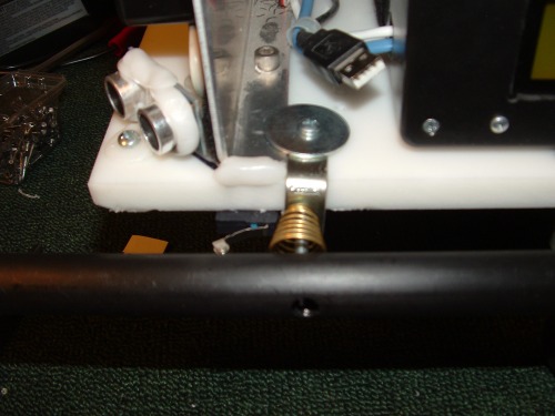
Surprisingly, the micro switches that I bought for the bumpers 8 months ago, fit perfectly.

So after the bumpers and sensors were installed, I had to connect them. I added the proper wiring to my new interface board [seen on the left connector].

And reworked the connection to the main Propeller Proto board as seen by the Green and Red wires connected.
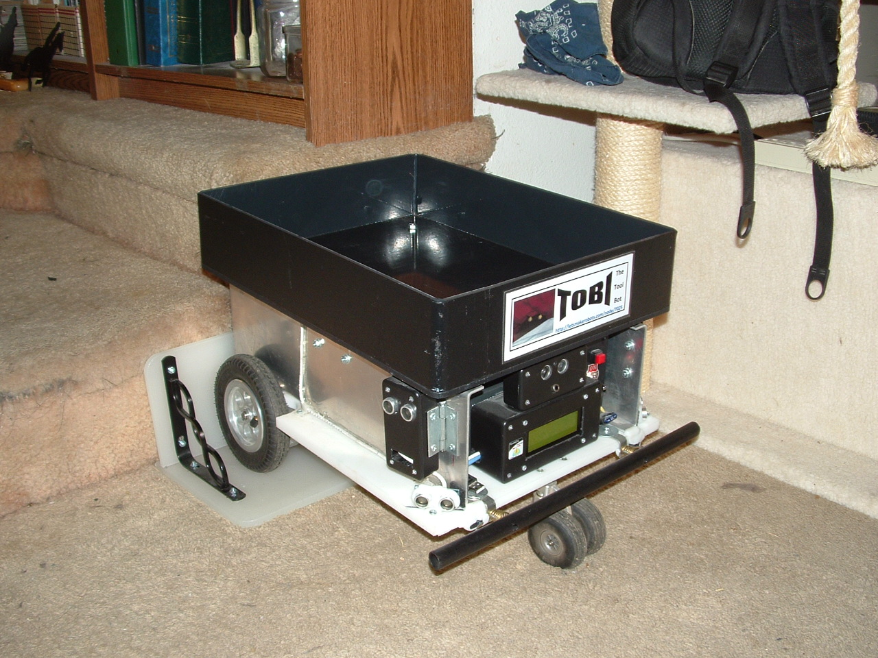
Next came a cosmetic upgrade. I made a more permanent sign for this Expo and affixed to the front of TOBI.
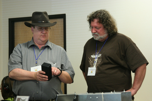
I took TOBI to the "Unofficial Propeller Expo" in Rocklin at the manufacturing plant of Parallax and here is a picture of my booth.

When I got to the event, TOBI went quite mad! I had to push him into the building. I found out that there were other XBee controled robots in the Expo. As seen in the picture, I had a programming cable attached so that I could change TOBI's ID to 4. I also had to change the RoBo Remote to another ID so I chose 7. After these minor changes in code, TOBI was fully functional for the rest of the Expo. I had several people ask about him and wanted demonstrations.
I also used him to load up with free parts from the scrap table.

I tried to work on the "Follow Me" mode while I was there, but I got readings from the TPA81 only for the first few scans and then nothing. Still, that is another chapter left to write in saga of TOBI's developement. I attached the latest code that I worked on at the Expo for TOBI and I also updated the schematics for TOBI's current wiring if anyone is interested.
Also, check out the RoBo Remote pages since I updated that page with the latest code etc...
UPDATE: 2010.08.31
This is more of an administrative update then anything else. I noticed that my information on the various stages of TOBI 1 through TOBI 6 was incorrect in the light of TOBI's development. So I updated the entire first part of this page about the various stages and set the status of TOBI 3 to completed on the date just before I took him to the Parallax Expo. Since then I have been using him at work as he was designed for but I have not continued his development. I have another project at work that is taking my time and should be completed by October.
UPDATE: 2010.09.29
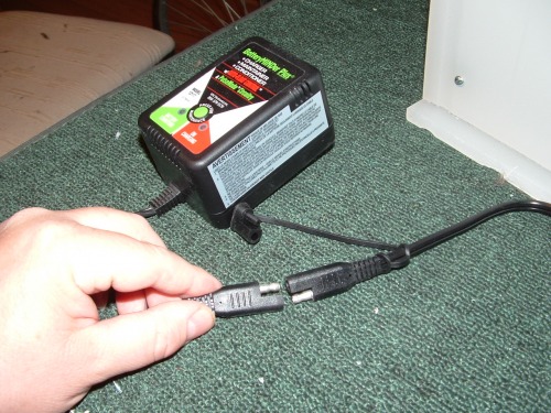
In April I found that either TOBI's battery was bad or the charger was. I took the battery to a local battery store for testing and I was told that it was about 40% good. They sold me a charger that conditions batteries as well as charges.

So I have been using it with TOBI for several months and it has allowed me to extend the life of his battery to the point that he can last a good day of shifting computers and monitors without failing. I do want to go back to that battery store and buy a new battery for TOBI. The one thing that has slowly driven me crazy about this set up is that I have to dismantle TOBI every night to recharge him.
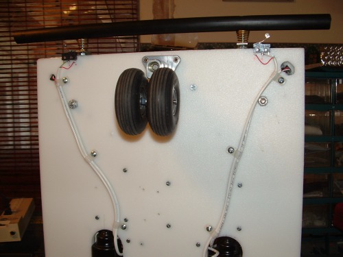
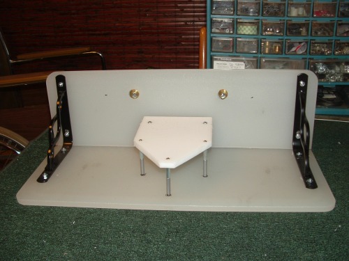
So I have been dreaming of a docking station that he can drive into for charging. I have been tossing the idea around for some time and I finally decided to build one. In November 2009 I was given two cutting boards. One was large and the other was a small one with a handle. I went to Home Depot and bought nice ornate braces for shelving. I cut the large board almost in half and mounted it as a back plate. The smaller board I wanted to use as a guide to line up TOBI with my charging contacts.

I used spacers for circuit boards and two angle braces to suspend the small cutting board so that TOBI will line up perfectly. The springs are left over from my failed first attempt at making a bumper for TOBI.
I mounted a couple of titanium plates on TOBI to make contact with the springs. I used my old wires from the past set up with the bad charger. I cut off the old plug off that I had used with the bad charger to connect to the plates

My new charger came with an adapter that could be directly connected to a battery or other wiring and I used it to complete the circuit.
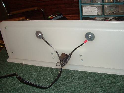
It even came with an in-line fuse!
I just had to line everything up so that TOBI could efficiently dock with minimal work.

After several days of testing, TOBI always makes a good connection and charges well.
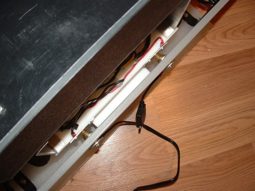
So TOBI finally has a charging station!
This project was so quick and really not worth posting in the "Something Else" category. But it is a VERY useful step in TOBI's development and makes me more inclined use TOBI on a daily basis.
On another note [TOBI 4], I got some good test results that show that my wiring of the TPA81 Thermopile is wired correctly. But now I have discovered some very bad news. The Thermopile is damaged. It gave me good results on the Ambient temperature and on the 1-5 pixels. I was able to see the data change correctly as I moved in front of TOBI. But the left 3 pixels were dead. Two of them gave a reading of 0 degrees Celsius and the other one 254 degrees Celsius.
This is going to stop my progress altogether since the sensor is $100 and I am struggling financially. I could use the defective sensor in some other project but I simply have to replace it for TOBI.
COMPLETED: 2011.12.08
I have decided to complete this version of TOBI at 3 and go on to build another chassis that can accommodate more accurate sensors. I will use Sharp IR sensors in the next version. The PING)))’s get a lot of interference from each other and I have run out of space to mount more sensors. Everything is getting crowded inside TOBI. I have drawn up plans for TOBI IV. He will be more Plug-N-Program and less home built circuits.
With that being said, I have decided that I will mark this Robot Page as Completed since this version of TOBI is not going to be scrapped or reused AND because it is in a very useful state.
When I start my “TOBI IV –The tool bot” I will post the link in this page.
UPDATE: 2014.08.30
Many have wondered what the total cost of this version of TOBI really is. I had to redesign as I went along so I probably spent close to $2,000 USD on parts. The final total of the parts that became TOBI III is half that. Here is the final list of his cost, the charging station and the cost of the RoBo Remote that I built to control him:
| Description | price |
| Caster | 79.99 |
| HB-25 Motor Controller [2] | 99.98 |
| Motor Mount Wheel Kit | 279.99 |
| Prop Proto board USB | 39.99 |
| Ping [3] | 89.97 |
| XBEE and Adapter | 21.99 |
| Battery | 58.99 |
| Scrap Plastic for body | 25 |
| Radio Shack parts | 128 |
| Charging Stand and Charger | 82.99 |
| RoboRemote | 164.97 |
| Final Cost of both RoboRemote and TOBI | 1071.86 |
Notice that the Delevan Thermopile is not listed. I bought 2 of them acually but I ran into limitations that prevented me from getting them to work. I never did get this version to follow me but it did a good job hauling computers and equipment semi autonomously.
Carry Tools and Laptop to free human hands.
- Actuators / output devices: Parallax Motor Mount Kit 12v DC
- Control method: RF controlled
- CPU: Propeller
- Power source: 12V 8Ahr Gell Cell
- Programming language: Assembly, Spin
- Sensors / input devices: PING))) sonar
- Target environment: indoors, office, Outdoors, warehouse
This is a companion discussion topic for the original entry at https://community.robotshop.com/robots/show/tobi-the-tool-bot-v-3

