

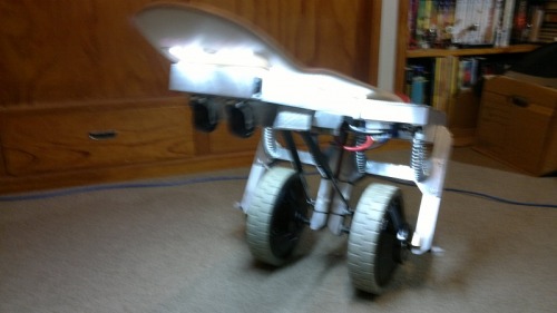
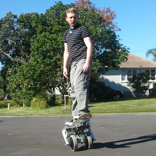
This is Tilter, my rideable self balancing robot. I've been working on this here and there for a good few months now, with a total ban on other personal projects, so it's really great to have it at a stage where I can start field testing it.
All the control is done by shifting the rider's center of gravity. When the rider leans forward, Tilter accelerates. Leaning back causes Tilter to decelerate and eventually drive backwards. Leaning left or right compresses the independent suspension, and Tilter drives towards the direction the rider is leaning.
Tilter uses a Digilent chipKIT Uno32 as the main controller, which is an Arduino-style dev board based on the PIC32MX320F128H microcontroller. As far as I know it's compatible with all the Arduino shields, code, and programming platform... but I didn't use any of the stuff to be honest. All I know is you can hook up a PICkit3 and program it as per usual using MPLAB.
Speaking of MPLAB, I decided to take the plunge and move to the new MPLAB X, which actually didn't take long to get used to and I have been very happy with it so far. I'm trying to improve my familiarity with using C32 (Microchip's 32bit C compiler) so the whole thing is programmed in that, and I've managed to stop myself from using any inline assembly code until I really have a good reason... being used to assembly for micros is not a good enough reason.
Anyway the PIC and the IMU are housed in the aluminium box under the nose of the board, behind a pair of rubber swivel casters. The IMU tells the PIC which way it's leaning, and how faster it is falling one way or another.
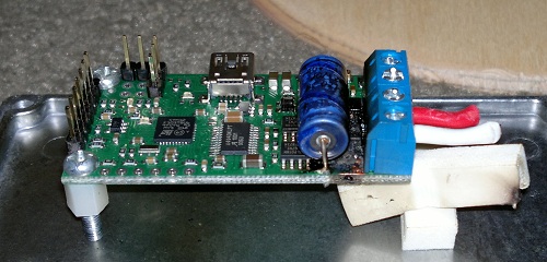
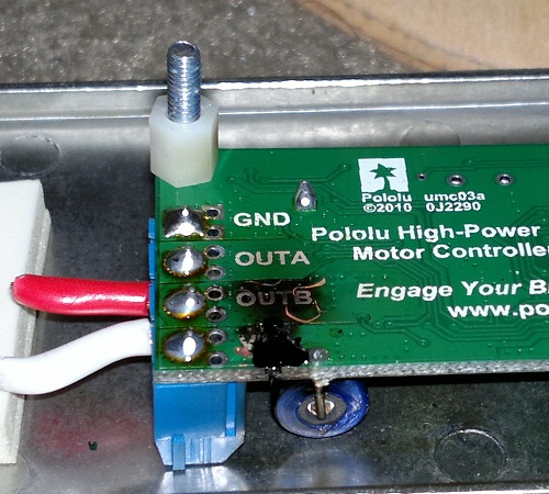
The PIC processes this input and then talks via UART serial to a pair of Pololu 18v15 Simple Motor Controllers, which are housed in separate aluminium boxes tucked under the 'wings' towards Tilter's tail.
Each 18v15 controls one of the two 180W Golden Motor HUB24E integrated hub motors, which have been modified to remove the solenoid brakes. The reason for removing the brakes is firstly to save on weight, and secondly to remove the need for powering the solenoids while running, which would increase the load on the batteries.
The batteries are connected in parallel via a two pole switch under the tail, so that when the switch is off the batteries are isolated from each other, as well as the rest of the circuitry. Mounted under the frame, right in the middle is a sealed automotive fusebox that offers some degree of protection against shorts.
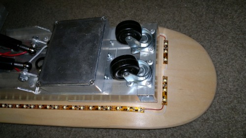
Underside of nose
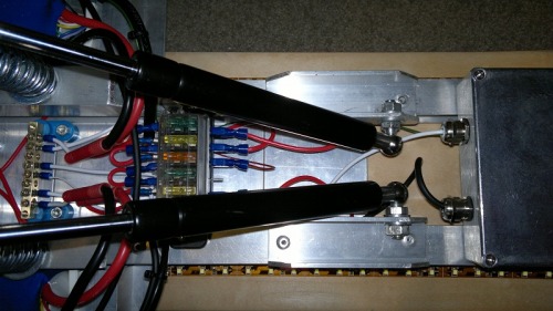
Underside of mid frame
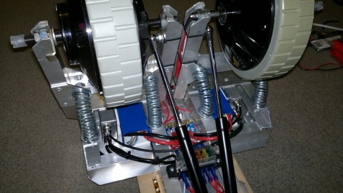
Underside of wings/rear frame
The frame is made of aluminium channel and flat bar, with aluminium blind rivets holding most of it together. The top board is a proper skateboard deck, bolted to the frame using coach bolts, with rubber washers in between.
The suspension system for the two motor swing arms simply consists of a pair of compression springs and a gas spring per leg. Rather than using bearings to allow the swing arms to pivot, I've bolted both sides of each arm with M10 galvanised steel bolts which are buffered by nylon insulating washers (along the thread) and nylon spring washers (between the plates). These create simple, low friction joints which so far have been more than durable enough to handle the fairly small amount of rotation that the swing arms actually perform.
The independant suspension system also allows for some simple 'passive' steering, which means that you can turn somewhat by leaning to the left or right. This isn't really enough for maneuvering around inside or anything, but it'd probably be alright if you were in a big, flat, empty field. Yeah, I'm working on that one.
Tilter is still very much a work in progress. On the list of things to do are:
• Apply black grip tape to deck - this will make it easier to stay on the board, and look sweet too.
• Improve control system stability - maybe a new control algorithm, or at least a bit more parameter tuning is required.
• Implement active steering - if using the IMU to detect if the driver is leaning one way or another is not enough, I've got a pair of Hall Effect sensor which I might use to detect how much the left and right swing arm suspension is compressed. Either way the plan is to apply differential drive to allow tighter turns while moving, and hopefully turning on the spot while stationary.
• Add auto shut-off if one motor controller reports an error or if the tilt angle is too great to recover from - this is pretty important to stop this thing running off and destroying something. 18kg feels pretty heavy when it drives at full speed into your shins, I can tell you this much for certain.
• Test the range on a single battery charge - these batteries are great, so it might take me a while to run them down. Not sure when I'll get the chance to do a real endurance test.
That's all from me for now, thanks for reading =)
Update: 27/04/2012
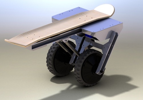
Implemented accelerometer/gyro controlled differential steering - didn't go well. The nose just doesn't roll that much when the suspension is compressed unequally, so I'm going to stick with the original plan of adding the Hall Effect sensors to detect which side the rider is leaning to. This should be more effective in the long run, as the signal won't need to be filtered as heavily, and you don't get as much of an issue with steering on sloped/uneven terrain.
In the meantime, here's a render that I forgot to attach from the SolidWorks model I made when designing this thing:
Update: 5/05/2012
Grip tape has been added and looks really nice, and I suppose it also helps you stay on... like that really matters.
When the angle of tilt brings the nose or tail too close to the ground the motors will automatically go to full coast. This makes it easier for the rider to rebalance the board, or alternatively easier to bail without Tilter racing off into the sunset.
Actually replace "into the sunset" with "into your shins".
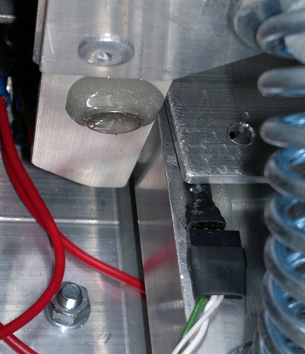
I added the Hall Effect sensors (2 x UGN3503) to the underside of the frame. Each sensor is paired with a small neodymium magnet so that when one of the suspension arms is compressed it brings the magnet closer to the sensor.
I soldered a small male header to each of the sensors before wrapping them in heatshrink, then I used epoxy glue to bond the sensors and magnets to the frame, as shown in the photo below.
After a bit of tuning I felt like the steering was going well, but I needed to do more testing out in the real world. Today was cool outside but with clear skies so it was an ideal time to get Tilter out onto the streets.

Everything was going reasonably well, but after a little while it seemed like the steering was becoming uneven. I thought there might be a problem with the Hall Effect sensor or the cable that carries the analog signal, but I couldn't locate the problem.
As the issue became worse I noticed that the PWM frequency of the left motor was off - normally I can't hear it above the sound of the gearbox, but even from a meter away I could hear the whining of the motor driver clearly.
A few seconds later there was some unhappy sizzling and popping sounds, and a jet of smoke from the left side wing. Thinking the LiPo was about to self-destruct I flipped the power switch to isolate the batteries, and the sound stopped immediately. I disconnected the battery leads and carefully prodded the battery - it was no warmer than the air around it, and didn't show any signs of swelling or burning.
I flipped the power switch back on to see if Tilter would run with just the right side battery connected, since each LiPo can deliver enough current to run the whole thing by itself. Immediately there was more sizzling, and I noticed smoke jetting out from the left side motor driver enclosure.
I brought Tilter back inside and opened up the left enclosure, and was greeted with the familiar smell of magic blue smoke and charred PCB. The motor driver output ICs were fried, and the heat had partially melted the motor terminals.
The next thing to check was the motor itself. A quick test with the multimeter showed that the winding resistance was roughly half what it should be, so when I get around to opening the motor up I expect I'll find a scorched set of windings that have shorted out.
So... where from here?
If the motor is gone, then that is the end of Tilter as these hub motors are no longer available. I may not even be able to get into the windings to attempt a repair without destroying the housing... even when removing the solenoid brake it took a lot of work to get access to the right parts.
At this stage I'm ticking the Complete box, as this project is definitely finished =/
Tomorrow I'll give the motor an examination, but to be honest I'm not very hopeful about reviving it.
I was hoping to learn a bit more from this project to help with developing the next version, and then gracefully retire Tilter when it became obsolete. On the other hand I'm still pleased that the idea worked at all, and I certainly learned a lot while designing/building/programming/testing Tilter.
This is beginning to sound a bit like an epitaph, so I think I'll just leave it at that.
Tries to stay upright
- Actuators / output devices: HUB24E 180W Integrated Hub Motor x 2
- Control method: Semi-autonomous
- CPU: PIC32MX320F128H
- Power source: 6S 22.2V 5000mAh Turnigy LiPo x 2 (parallel)
- Programming language: C
- Sensors / input devices: Sparkfun SEN-09268 5DoF IMU, 2 x Hall Effect sensors
- Target environment: The suburban jungle
This is a companion discussion topic for the original entry at https://community.robotshop.com/robots/show/tilter

