This is effectively my thesis in my study to develop a mobile scanner.
The scanner will act as part of my research to develop mobile scanning.
Overall it is an effort to improve personal defense abilities.
I am working on a mobile scanner much like a science tricorder to ‘diagnose’ elements in a field of view. The purpose of this topic is explain how the prototype of each model works. The main focus is scanning for life, and or material and the signature of that material.
The first scanner was built in secret. A combination of heat and ultrasonic in a primitive effort to show the sum of major pixels. Space was measured by distance. Heat was equal to distance, and both measured into red(a target) or blue field of view.
However, the second is more interesting and focuses on a type of haptic feedback. A ferrite induction coil has two properties. It can send a wave called flux that is transferred, or it provides feedback.
I have improved the coils abilities in a working prototype. I am awaiting an unnecessary part before I document it. I will not immediately tell you what I did, but I will show you and tell you how it works.
Parts used in board I call ‘analog controller’:
555 timer for analog reading (trigger)
Potentiometer/trimmer for main power + sound if you wanna control it
Copper strand wires
LEDs (OUTPUT)
Buzzers (OUTPUT)
The scanner works exactly like a metal detector. It sends power through a coil which is disrupted by a nearby object. The total range under testing was 4 meters. It is arguably powerful enough to reach 10m(to conclude thesis). It was tested for metal and life(ppl, objects).
This was accomplished by reflecting the flux. Think of a laser on a mirror. The scanner was built with dual specs that are used to sum a reading. The total reading finally becomes a scanned object.
Improvements in design can or will be part of future tricorder designs if desired. I plan on testing other sensitive sensors with accurate digital readings with an Arduino.
Other comments
I came up with this addition to my personal R&D from the tricorder. No specific Science Officer inspired it. It started out by watching the medical tricorder in action. I thought it seemed pretty nifty to shoot radiation in such precise amounts that it graphed an accurate image using xrays and such-possibly at the subatomic/subspace level.
It didn’t seem apparent to test this with dual coils until I saw Spock’s unit.
NTR This is also the image that articles say the tricorder is coming to your neighborhood.
The tricorder was a noisy little thing. It seemed to graph space with sound imaging like echolocation.
All I needed to do was ‘reflect’ the flux from the ferrite to build an analog reading. After that, testing from an Arduino and different sensors might produce a number. That number is our tricorder log. The computer’s job is to display the reading. That’s what my timer is doing. The output is displaying a number of possibilities; only capable of displaying from a logical reading from our known laws. Any reading beyond this, breaks those laws, as I am currently aware of it.
Finally, here is a picture of assembly in different stages of models
-
This prototype doesn’t work like anything I’ve seen before
-
I will continue to improve it and personally use.
-
You will observe ‘the prime directive’.
3 Likes
Testing issues 4.5.20
The coils are sensitive to high bursts of ‘overload’. If the voltage is above that of the controller, it will act as a single coil - thus it will ultimately act like a metal detector. Strangely enough, it is no longer distance sensitive to metals.
Summary: If voltage/signal of active coils is low enough, there will be a straight continuous beam. TImer/coil mustn’t overload. Signal/coils mustn’t cross.
Reply with comments or for concerns about any tests.
I got a 4xAAA case expedited.
I’m going to show a few different reasons why 6V won’t work. Primarily because the (battery)case is too large, but 4xAAA is 6V and that’s above specs.
I try to continuously vary the amount, but I get many different results. They eventually get very bad. It is impossible to record all results. At some point the entire output goes LOW. There is no sound or light.
In the last video clip it actually worked as expected for an entire 2-3 seconds.
Things to expect from working scanner at runtime:
0 metals
1 scanning
.8 person
.3 plant
These are general numbers from unrecorded testing. It should improve when the 3xAAA arrives and installed, but there is no guarantee because the batteries may still interfere with the signal. All testing with done via wire through external wires that did not conflict with any signal.
That’s why adamant amount of testing is necessary prior to final designs. If this works, more models can be manufactured for testing.
Most of these clips are mixed up…
Also, those numbers are rough estimates between two not one reading. The two comparative LEDS will sum. The 3rd is a power LED.
Update(unnecessary):
The extra battery was replaced by a coil and affixed with resonator.
Coil has minor impact on secondary coil. 4.5 accuracy.
Final video of analog scanner will accredit final result.
Hall effect magnet sensor for digital science scanner
Testing was completed for what could have been a digital scanner. The tests show much more promising results. It could mean an additional sensor for the analog scanner.
By theory the model for the analog scanner has two comparative coils. The second coil adds additional sensory abilities to the overall scan. If it were one, anything close could be equal to anything like it. With numbers, if a scan of another person were .8 but some rock was .7 or .8 - the scanner says you’re a rock. That’s not very analytical or accurate.
By theory the new model could have a magnetic sensor that matches a comparative reading to the original one. The coil sends and receives an interrupt signal. The magnetic sensor would instead add variation to the reading.
If an output is trimmed at low to negative, the output is less. You turn the knob clockwise, the output is greater. By contrast the same goes for the HEM sensor. Except if we cut our output to negative, we will loose our reading.
I believe it may be more accurate to connect our HEM sensor to a positive output. That way even if the light is HIGH, the output will continue to receive signal. That means our reading will occasionally shut off - unlike if it were off completely. We wouldn’t be able to distinguish LOW from the signal.
Optimal output might be HIGH+x = y, r = y*x
HIGH-full, x-signal,r-reading
The next update is a model C that uses an Arduino. I have a Yun left…
The original theory behind this model was the HEM sensor.
The Arduino reads a number from the scanner. A screen displays the reading and if the library recognizes the reading, displays the material.
EXs-
741
Trilithium,
600
Rock
I finished the Beta scanner. I don’t have media for it yet, but it is definitely working very nicely.
I have a HEM with open unmodified coil, same reflector - no boosters.
4xAAA
One piezo/LED
Dual trimmers
and slide switch
*Added boosters to scanner Alpha reflector.
*Replaced 4xAAA battery case with 3xAAA
Tests were done. It seems it could possibly be more accurate, but the distance of this accuracy is much different than expected. The theory behind this one is that the HEM is effected by the flux which isn’t always rapidly changing. While under normal circumstances the flux will not change because it is like butter or fat. The HEM will check this reading as a secondary review. So far, certain things are more or less effected.
The HEM effect is what drives the ineffectiveness of certain scans while also providing distance to that which is more effected. Things like broadband or radio might effect the HEM by measure. However, metal is less than 5-6m at max range. Larger metals were farther.
Non metal or other scanables just simply don’t pass any quick analysis.
My overall conclusion in both tests would have been much more effective if the entire backing of the scanner was converted into a reflector. The majority of objects interacted with the scanner seemed to be far more effective with materials that received converted flux. That meant materials that absorbed the reflected flux displayed properties similar to the initial coil. The overall scan seemed evident of that and most apparent in the last clip taken for media.
Forgot to talk about this…but I was hoping the second scanner would be more similar to something like the harvesting waveform. It would show an accurate analog reading of something like this
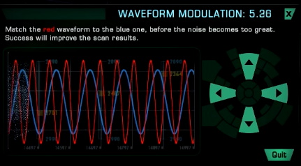
Something to hint here is the “noise”. The noise becomes too great?
My scanner uses a flux wave similar to a magnet.
Electric are positively charged ions moving from it’s source to an attracted negatively charged material (to simplify). When the positively charged ions travel around the ferrite, the metal charges. The ions of the metal are attracted by this force. The field or area charges around it. The area slowly begins to pulsate. Another metal can “feel” this charge. It can also absorb the charge from the field. A repeated process is finite. Eventually the charge wears and is completed by neutrons.
The field is question should have a few attributes to simply the review process.
This is a field. The field is disrupted by an object. The analog reading shows the effect the object has on the field. The symmetric questions follows
-
What type of field?
-
How does the field react to the world/objects?
-
Is the controller correctly assessing the world in field?
The first time these questions are answered (by Model A) should look like
A reactive field
The reactive field isn’t passive.
Irrelevant, the reading displays strength not in particular.
The answers should be far more accurate by Beta.
The Model B uses the same reactive model has Alpha, except Beta uses a HEM.
A reactive field
The strength is far more improved to Alpha and distance matters.
The HEM gives additional benefits to the reading by passively scanning the field.
The last thing I didn’t mention on this subject is the secondary coil in Model A.
Model A has a comparative, secondary coil for ‘challenging’ the field.
It is accompanied by its own timer and its own reaction on the controller.
It is simply another reactive sensor.
Conclusion:
Model A has two comparable reactive sensors.
Model B has one reactive and one passive sensor.
Model A has potential to react versus assess. It may be limited and ranged, but accurate.
Model B has potential to assess and react. Unknown at moment.
Relook at the ‘spectrometer’
Tmk, a spectrometer is telling to world how things really are. Instead of simple color, the spec’r is showing a number. It is another aspect I am reviewing as part of this project. It might be useful. However, someone else’s thoughts will be more useful here.
As of June, a good amount of improvements have been made to the scanners. The design and troubleshoot is back to spec. A fair amount of testing has been completed.
The scanner tests show that most interactions made by intersecting waveforms are during a digital theta pulse. That is hard to measure due to the strength of the coils. However, a low burst deemed within a range of Theta measurement exhibits signs of sensitivity.
It places a LOT of speculation on the form of flux waveform - but you must remember that the coil is wrapped. It isn’t necessarily strength involved. All coils operate a frequency due to AC.
Another prominent aspect is that you aren’t regulating an (intercepting) signal. You are matching the (resonating) frequency of the flux object waveform. That means the object in range must be sensitive to flux resonation.
Plastic is a very common ‘element’ that would object to resonating flux. It might even be possible in the future to measure it via resistance. It will be more obvious when the digital reader has been completed. A visual representation will show a lot more information than a few buzzers and Morse blinking will.
Overall, the import piece of information in this update is that it seems most incoming signals or matching frequencies do not object to Theta length flux.
A very long ferrite coil like mine and 2v-3v on the 555 timer should react fairly well in any primitive clone.
I’m pretty confident this has been my most straightforward update. If you agree, please like and share. Thanks 
My analog scanners have since been “primitive”. The last many updates, I have discussed my analog scanners in great detail due to the nature of technology. I have developed a few personal devices that I have used to stimulate and “reflect” a magnetic field.
Since then, my focus was on creating new ways to express and develop information. I have been rediscovering radio. There many different kinds that include wifi and a new(20x) protocol known as LoRa. While working on my usual security schematics, I crossed paths in my mind between another subject. I have been playing and putting together a transistor computer for myself.
The 3906 NPN. The idea had never struck me before. An analog scanner with a sensitive diverting transistor. At first, it was a failure. The GND pin - base does not emit signal. Only a PNP can freely allow these sensitive particles to travel without hindrance. My scanner could freely detect at will. It seemed to even know thinly sliced paper from the metal pins of a transistor.
I did that by connecting my base coil to output that goes into the piezo at the 555. While this 3904 changed my life that night, so did another thought. No one can read buzz. My entire thought became of a clear plastic enclosure with little bright embedded LEDs. How could my new scanner tell us exactly what we are seeing?
I developed a flipflop for the NPNs. How it works indirectly is that the secondary NPN is powered by the primary. Signal is sent to both(secondary to coil - primary to collector), and opposite ends are connected (which flip flop). When a certain amount of signal exceeds the primary, it “moves” to the secondary. This isn’t exactly how. That would mean the first might light into the second like a trimmer. NO, that is incorrect. The NPNs are receiving a different amount at the same time. So each on its own secure channel will flash, light HIGH, dim, go LOW, all at the discretion of individual matter.
No longer does a scanner tell you when or if.
No longer does an individual meticulously coordinate frequency or redesign to compensate.
The Alpha 2.1 will say exactly what it sees with an attractive analog display.
Trees people computers snowmen aliens on your radio?
The Alpha 2.1 knows the difference!
I’m from Maryland. I’m just an independent, and slightly insane scientist 
I’m actually just a simple roboticist. I study software and hardware. I also study things like psychology and media. I am trying to rebuild old things into new things and sell them.
This project wasn’t anything special. There is a limit to the power. The coil isn’t very effective, but it was wireless. The reflector I used was iron-zinc brass plating connected to the coil.
Serbots Labs is no longer going to be taking an interest in this project as it is too scientifically complex. It involves things that one are unrelated to robotics and schematics research, or two the product we are involved in is unmarketable. Unfortunately, I am left with very little to sell. That means I can’t improve anything. Let me know if you need anything else. I’ll be looking out.
David, Serbots Labs
1 Like


