The House Bot

Here is my current project and first post:


Originally conceived with 4 wheels, half way through the build process I thought it would be cool to balance, so no casters yet. After a few weeks of fiddling with the IMU and Kalman filters, it outputs a good angle, but takes way to long to settle at the correct number. There is no way it will balance until a correct angle can be generated without a settling time. A dual omni wheel suspension system is in the works so that progress can be made on navigation and docking if the balancing ends up to be more trouble than its worth.

Short term to do list:

Balance or add casters

Fix up the PID

Hookup and mount the IR and Ultrasonics

Make a base charger


Eventually, I would like to add a camera or small laptop with webcam to do some image processing for nav and docking, maybe telepresence.


More Details:

Base decks: 1/8" Aluminum sheet, 1/4" angl, thread rod

Electronics: Technological Arts Adapt9S12DP256, Sparkfun Bluesmirf serial port connection to PC, Sparfun 5 Axis IMU, protoboard motor driver with LMD18200's.

Locomotion: 24v gearhead motors with encoders, 5.5" electric scooter wheels with integrated toothed pulley, belt drive to gain a bit more torque and reduce wear on the gearheads


I added some pictures to a blog entry, which I thought would show up on this page, but didn't: https://www.robotshop.com/letsmakerobots/node/1735


September 28 Update:

I ditched the balancing idea after weeks if fiddling with the Kalman filter. I came fairly close, but I just could not get the correction to update fast enough. The Kalman filter produced an accurate angle, it just took too long to get it. By the time the correct angle refreshed, the robot was falling to far. I picked my motors and belt ratios for raw torque, not speed unfortunately.


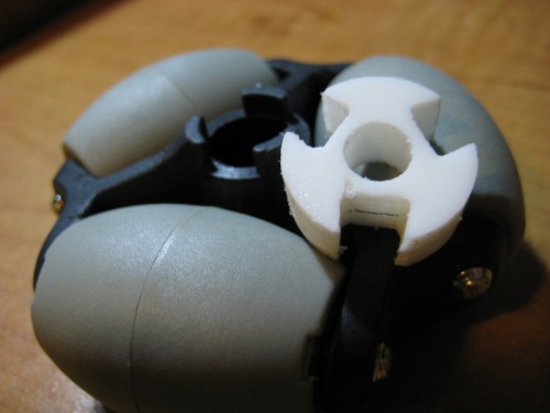
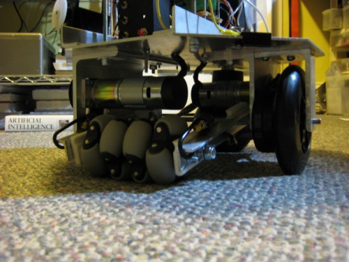
I added a 4 inch ball caster to the front, and two 3 inch omnis to the back. Both omnis share an axle which is mounted on bearings. This axle is connected to the drive wheel axle through 2 aluminum angle arms and 2 more bearings. Right now suspension is accomplished by bungie cords until I find some shocks at a good price.


Omni wheel with lock tab adapter I made.


Underside showing the Omniwheels and suspension.

Robot Suspension


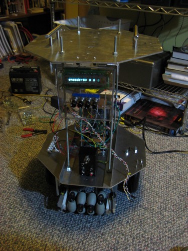
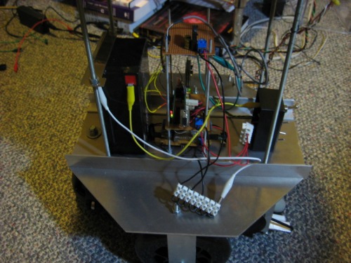
I mounted the VFD display and some 10 turn pots in a plastic case on the back and neatened up the wiring a bit. Next up is a pan/tilt head with a bunch of sensors. I am planning on using GP2D12s, SRF04s, and a couple of Polaroid rangers. I coded up servo control via PWM since there was a free timer in that module, saving the general purpose timer for other things. Fortunately both sonar modules use nearly the same code, so not much work had to be done there. The biggest issue I ran into was I overlooked a pull up resistor required for the Polaroids(Doh!).


Display and Potentiometers


Messy(but improved!) wiring.

Messy wiring


The two videos are of dead reckoning maneuvers using the encoders.


http://www.youtube.com/watch?v=Lo7m98Tu870


http://www.youtube.com/watch?v=n7hITTz9W4k

Will navigate around house, self dock with charger, map, fetch beers

  • Actuators / output devices: 2 24v gearhead motors, VFD display
  • Control method: autonomous, bluesmirf for programming and debug
  • CPU: MC9S12DP256B
  • Power source: 12v SLA
  • Programming language: C
  • Sensors / input devices: Sparkfun 5 axis IMU, 2 rotary encoders, 5 Sharp IR GP2D12, 3 SRF04, 2 Polaroid 6000, 4 pots for tweaking parameters
  • Target environment: indoor

This is a companion discussion topic for the original entry at https://community.robotshop.com/robots/show/the-house-bot

Clean, tidy and ambitious…
Clean, tidy and ambitious… I like it!! Are you a machinist?

Thanks for the comment, Im
Thanks for the comment, Im actually a computer engineer. I dont have any real machine tools…yet. Almost all cuts were made with a jig saw, the rest were with a hack saw. Holes were made on a small drill press except for when they were too far in on the plate, then I used a regular drill.

(I saw your blog-posting,
(I saw your blog-posting, but there is no automated link to it here. that is an error, we are working on fixing it.)

Self charge dock

I like the idea of a robot that knows when to recharge itself. I was actually hoping to make one that can do, among other things, just that. How does your robot know when it needs recharging? I suppose it’s monitoring its own battery level (right…?), but what components do you use to do this?

/Dan,

Re: self charge dock
Hi Dan, I haven’t implemented the charging stuff yet, but I will most likely make a resistor bridge across the 12v battery to bring the voltage down to around 5v maximum out of the bridge. This will then go into an A2D line on the micro. I’ll just manually read the A2D when I know the battery is getting low and needs to charge, then I will set the program to use that number for the threshold. ( If(battery_voltage < threshold){ find_charger(); } )I suppose it might also be a good idea to run the voltage through an op amp or something to protect the micro from getting fried if anything happened. The charging cycle will probably be controlled by a timer.

Why are you using a VFD?

Oh my, that sounds like a

Oh my, that sounds like a very bad idea. There is a lot more to charging batteries than that.

There is a special chip called a UC3906 that does all the work for you. There’s a copy of the datasheet on my website http://asmith.id.au/files/uc3906-battery-charger.pdf but you can find it in many places on the internet.

Here’s a sketch of the circuit that I use for a 6 volt sealed lead acid battery http://asmith.id.au/photos/sla-battery-charger.jpg

I’ll get busy and draw it up properly at some stage. The values will change for other combinations of batteries but the datasheet goes into great detail about the calculations involved.

However your method for measuring the battery voltage is fine as far as I know. Certainly it’s worked for me.

I was thinking about having
I was thinking about having the charging circuit contained in the dock, running a circuit similar to what you posted that switches to trickle charge once the battery is getting full. I just meant that the robot would stay at the base for a timed period, allowing the charger to do its thing, then I would not need communication between the dock and the bot to signal charge level. Although it might be easy to add an IR led to the charger circuit that turns on when it switches to trickle charge, and have the bot pick up the IR signal to leave the dock. Thanks for the circuit, I’ll pick up some of those chips next time I order parts.

The VFD was a cheap and easy
The VFD was a cheap and easy alternative to using an lcd display. The module I have is serial and simply takes Rx, +5, and GND. I already send debug messages out via serial to the P.C. so it was extremely easy to interface and required no extra code. Everything that the microcontroller outputs over serial appears on the VFD. Plus the characters light up! I got it here: http://www.bgmicro.com/index.asp?PageAction=VIEWPROD&ProdID=12312

Hey, where did you get the
Hey, where did you get the ominwheels?

Kornylak , I ordered the
Kornylak , I ordered the R30, its just over 3 inches in diameter. Its by far the cheapest source I could find for something in that size and strength. Note: they are sold as a half wheel(3 rollers), so you need two to form a full wheel(6 rollers). I ended up putting 4 halves along one axle since 2 are wobbly as the load changes from one half to the other