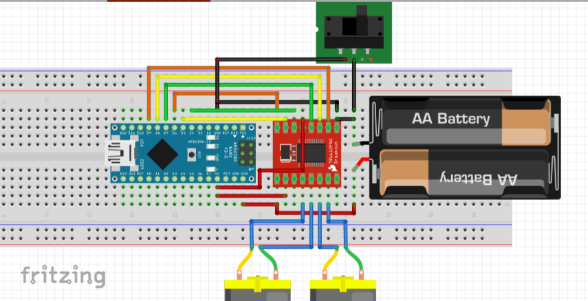
Currently I am on my project that deals with DC motors. So I have to use a motor driver for it to control the motors. I am using TB6612FNG and did this connection
Yes, I did placed the slide switch on the negative wire of my power supply which is 12V. The positive wire of the battery is going to the VM pin of TB6612FNG and Vin of Arduino Nano. So what basically happens is that the motor driver will only work once the arduino nano is turned on (which I can control by disconnecting or connecting the GND from the power supply.) since its STBY pin is fed on to the nano’s 5V terminal.
So what happened was that at first it went well. But I can observe this heating up (not that much). Suddenly, I see my arduino nano’s built in LED turned ON (not fully turned ON, about 75% of its brightness I guess) even though the switch was not turned ON. then as I took my Motor driver off from the PCB I made, I can feel how extremely hot it is. Fortunately, I didn’t smell/see any smoke coming from it.
Is there anyone could tell me what just happened and what i did wrong? I checked its connections multiple times. There were no shorts. BTW, I bought another motor driver and the same thing happened. IDK what to do. Any help is much appreciated!
It’s hard to follow exactly what you have set up from your description, and fritzing is the devil. a proper schematic diagram is MUCH better.
But, it seems from the description that you have everything wired up, but you put the power switch in line between the battery and the nano, on the gnd wire. But it appears you have the ground wire connected directly to the motor controller.
If that is accurate, then the motor controller will be powered normally and nano will be getting power from the battery but doesn’t have its ground pin connected. That’s a bad situation. Current WILL flow through the componentes on tbe nano through whatever path it can find (through the logic connections to the motor controller, which is powered.) Those paths are rarely the right ones and the parts are NOT operating as they should. That will cause a lot of problems, perhaps including the ones you are having.
What I recommend is that you connect the grounds of the two boards together permanently. Connect the two positive inputs together permanently. Place the switch between the battery and the two boards (it doesn’t really matter which wire, but plus is conventional.) That way if either board is powered they both are.
Thank you! Right now, what I just did is giving 12V to the VM pin of the motor driver and the negative wire to the GND, with not more than a second, it really heated up extremely. Then got dissipated right the moment I took the wires out.
P.S. only the battery wires are connected, nothing else. no motors and others. I am really2 bad. How do I know I got it broken?
I’m not really familiare with that particular motor driver. But a lot of driver circuits don’t like having power applied without proper control signals also applied. I don’t really think you damaged the motor driver unless power was hooked up to it incorrectly. It’s a lot more likely that the arduino was damaged, although that really isn’t all that likely.
To find out, I would test the two parts separately. Disconnect them, write some simple sketches for the arduino to test the pins that are connected to the motor driver (blink some LEDs or something.) If that all works correctly the arduino is probably fine. Then, put JUST the motor controller on a breadboard and attach its input pins to ground or +5V as appropriate to power it in an inactive state. If it still gets hot it is probably damaged. If not, it is probably heating up because of a wiring or program error.
Once both parts are tested and appear to be working, put them back together making sure all wiring is correct.
!!! An important note!!! ALWAYS connect all the grounds together! Bad things happen if grounds aren’t tied together properly.
I have no doubt that the fritzing image you posted is correct. But the information is much harder to get from a fritzing image than from a proper schematic. Schematics are much more useful, and they are standard. People like me who have been doing this for 40+ years read schematics. I don’t really want to work extra hard to learn something new that is less useful and nonstandard. Sorry, that’s just how it is. If you want to communicate with experienced people, it’s best to learn the language they use.