

This will be a note for my just started team project "Swarm Robots".
This project will take place in our hackerspace Shanghai "Xinchejian". it will be a team project where every member can join and contribute his/her skills, ideas etc.
In this blog I will ask questions and write down solutions, ideas, goals and everything else what is related to that project.
So far that's the initial idea:
- build a swarm of little robots with a size of max. 5cm x 5cm x 5cm (create a 3D model to print the base)
- the swarm is "living" in a walled world to prevent them to fall off the table.
- the world will be equipped with different IR (infrared) beacons for the communication and navigation.
- robots can/should have different capabilities, e.g. equipped with a gripper, charging equipment, light, shovel etc.
- robots with different capabilities should have a different behavior.
- each robot and each IR beacon get an unique ID (DISCUSS: to imitate real world swarm, unique ID should not be given, or at least be used in the inter-robot communication)
- keep the costs for each basic robot (base, 2x gear motors with wheels, 2x dual motor driver, 1x sensor, 1x IR receiver, 1x µC and 1x battery) under $5
What to do first:
- create rules and actions for the world
- build a simple IR beacon and one robot to figure out the transmission protocol we want to use
- build more robots and beacons for different tasks
- make the swarm interacting
- create a web interface with a webcam to control the robots via internet
Official start of the project by Sunday May 6th at 15:15h or 3:15pm:
We created some sub-gteams as we want to share the tasks. Electrical team, Software team, communicatipon team, mechanical team. All these teams will research first and come up with a solution. Next Thursday is "collecting day" where we discuss the results. for now it's not much more to say...I will update this blog when we get more details.
UPDATE May 10:
We changed the project slightliy to achieve a goal whcih was not expected before. Now we convert it to a football/soccer project since a shopping center wants to display the football playing robots during the UEFA cup next month. Right now we do not have any design and need to develop the whole platform, electronics and software. Then we have to build 30 robots until June 8. Wish us luck and don't be angry when you not see much updates here since every single minute will be deticated to the project hahaha...
UPDATE MAY 12:
Since the change we did try to figure out how to handle the three different signals
- Find the ball
- avoid the wall
- don't kick the ball in your own goal
To keep it cheap we wanted to have those three signals running via IR (maybe on different frequencies). Next week we need to check the location where the robots will play the game to see how much IR distortions we shave to face. Shoppting centers usually have some spot lights, sunlight or even the secority cams are flooding the place with all kind of IR light. To have to deal with less IR signals I was thinking to use a hall effect sensor on the robots and magnets in the ball to sense the ball. However, I could not make it working. The hall sensor I got is the A04E 128 and I did not find a good working circuit. Basically it's just VCC, GND and OUTPUT. Then a 4.7k resistor beween VCC and OUTPUT and the ting sould work. But it does not.
Does anybody have experience with hall effect sensors and would like to share it with me? Thank you!
UPDATE May 13:
We got the ATtiny2313 programmed - after some failures. Will write about it tonight.
UPDATE May 15:
Two prototypes to test the platform, sensors and programming are soldered together. We got the design for the upper body and the shirts done as well. Tonight we will build our first IR beacon to test the navigation.
The test with the hall effect sensor failed since the range is very short (max 4cm) and it's directed... that means the sensor outputs different values when facing the north or south pole of the magnet.
Sorry about the missing pictures and video but basically we just go back home to sleep...no time at all to process video and pictures. I will try to get some up by tonight.
UPDATE MAy 16:
Our attempt to generate the 38kHz wave with an Attiny2313 failed. With an ATMega328 it was successful but failed after running for a while. After 30 minuted the frequency dropped to 31kHz. Is there any explanation why that happend?
Now we are going to use a 555 timer to generate the 38kHz IR wave.
UPDATE MAY 17:
We got the IR beacon done. Using a 555 timer is an easy circuit on one side but on the other side it#s a pain to adjust it to the right frequency of ~38kHz. Choosing slightly different values for the components will create a much different frequency. However, we got it done and the beacon sends a quite narrow beam.
UPDATE MAY 18:
It was 1:30am when we got the first simple navigation running. The robot is chasing the new built beacon. If the beacon is moved then the robot will change his direction and go for the beacon. Well, that's another step forward. See the video!
Not we develop the most likely final navigation algorithm. Besides this we build a vacuum molding machine (like these: https://www.robotshop.com/letsmakerobots/node/10090, https://www.robotshop.com/letsmakerobots/node/23285) to form the upper body.
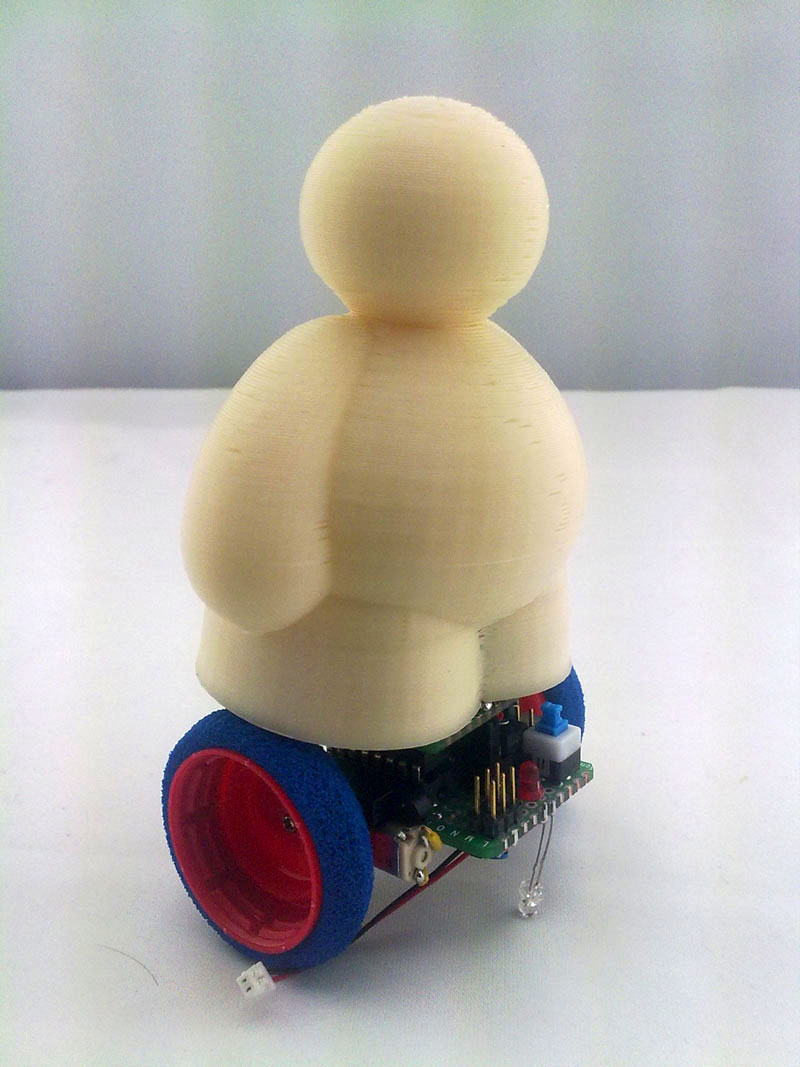
The upper body will sit on the robot base and contains the sensors (at least some of them)

This is the 3D model of the upper body and it will be used for a mold. The two halfs of the upper body will being vacuum molded.
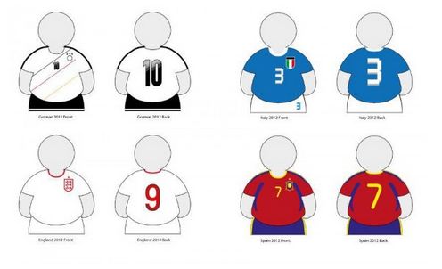
This is the design of the shirts we want to put them on. They will be tailored according to four European football teams.
This upper body will almost cover the whole base, maybe just 1cm clearance to the bottom edge of the base.
Ball Info: The ball will contain an array of LEDs and an Attiny to generate the signal (38kHz and modulation). So the ball is active and the robots can see it.
UPDATE MAY 22:
Ok, 4 days no update because I was working till dawn ;-)
First of all, the sponsor has pulled back the offer (or better said, did not reply our messages and when they said "need one week more time to decide". One week in this time frame is quite a lot, so we assume it's off now.
However, we are going to finish that project but will slow it down a bit...no working after 2am anymore ;-)
We got some simple modulation done. 38kHz with 27Hz wave. Using a 556 timer would be efficient but to calibrate the frequency is quite a pain. Using an Attiny is better and gives us the means to put a bit more functionality in.
Part of the project is also fixing our Makerbot an RepRap as well build the vacuum molding machine. These three things will be done next weekend (crossing fingers).
UPDATE MAY 25:
Here another update about the progress. Our team got some modulated signal done which we will use for the whole navigation and communication. More details about that later. Now just some details about the hardware:
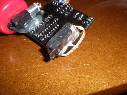
We build another test robot but this time smaller than before.
Left is the first prototype and right is the new shrinked one.

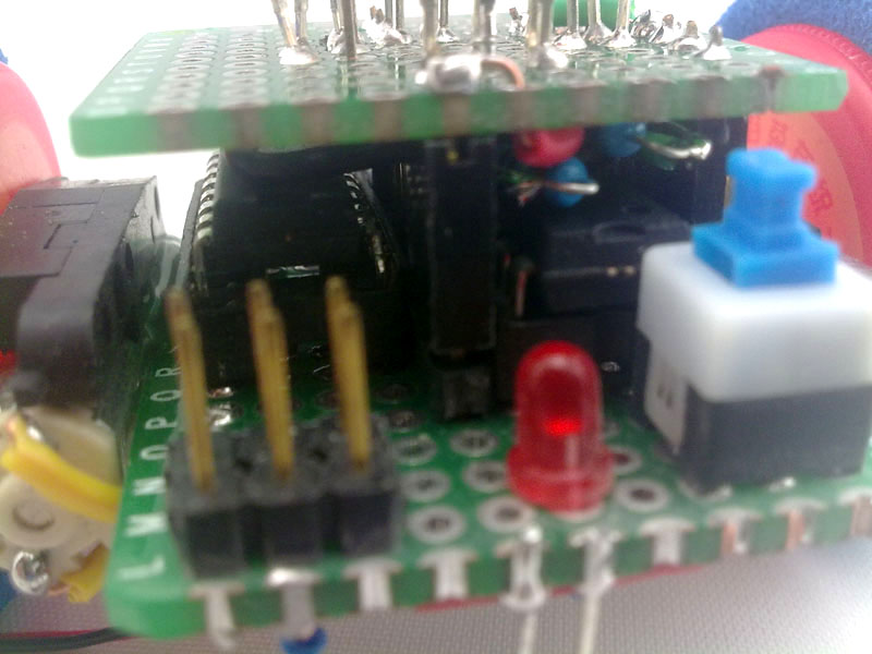
The PCB is 3 x 4 cm and still not full occupied ;-) The final PCB will be designed this weekend.
More pictures...

We tried other IR sensors but they are not good. Dunno the number but that was the cheapest one. It will even get jammed by white LED light :-(
We also put a 6-pin standard header for programming on the PCB.

Yes, we like LEDs for debugging ;-) Each LED shows if the respective sensor is active.

Bottle caps and foam tires.


Compared with an 1 CNY coin

That's the form for our vacuum molding machine where we want to mold the upper bodies. That one is made on a friends Makerbot
Seems it's full packed but there is still space. We put a shield on top of the Attiny2313 to mount the sensors since they will be wired on the pins and later moved up to the head (on a smaller PCB)
UPDATE MAY 28:
The plan for this weekend was, to get 4 PCBs done by last weekend. Struggling with KiCAD as layout software this goal could not be achieved. Now we got it working but weekend is gone. We can not get all the copper traces in one layer and we do not want to etch a 2-layer PCB. The plan is to make a 2-layer board in KiCAD and just print the bottom layer, placing wire jumpers as upper layer. It's still tricky since the PCB will be only 49mm x 49mm in size.
UPDATE JUNE 15:
We etched, drilled and checked the PCB. After that we populated the PCB and yesterday we finally powered it up. What can I say....there was no light at all. Short moment of fear but we discovered one broken jumper wire (no idea how this happend). Soldering, checking...connected. Then plugged the ISP programmer cable to the ISP port and uploaded the "Blink" program to the Attiny using an Arduino Nano 168. Well, there was no upload but an error message. Checking the PCB again. Now we again measured all the pins of the ISP port, whether they are connected to their respective counterparts or not. After finding another broken trace (yes, i already said that we need to improve the quality) and fixing it the program uploaded just fine. The RX LED was blinking (blink modified to blink on pin 0), Give me five \\|//
Some pictures:

Bottom layer (the two green wires had to replace two bad tracks...

Setup to program the board with an Arduino Nano 168

UPDATE SEP 7:
We got 30 blank boards from the factory for testing .
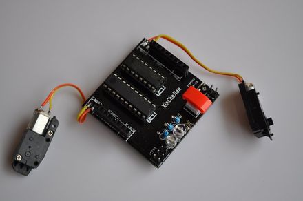
So far they work well but now we also understand some things what we need/will do better in the second version. We build some different test robots for programming purpose and trying out different "shields" like IR shield and "micro switch wall follower shield"

Wall follower shield

The motor connectors don'd need pins, holes for solder the wires on the board are good enough.
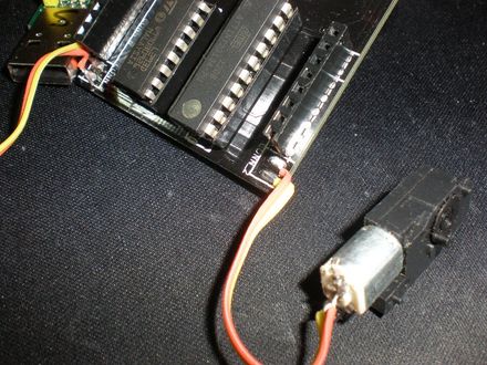
Hotglue as motor holder...flexibel to dampen vibrations LOL
Videos will come later.
The new board is already in development. It will include an Atmega328 or Atmega32u4 and a much smaller and cheaper but better motor driver. Everything will be SMD, so either we just let it manufacture or take the task, wear our magnifier glasses and try to hold our hands still by soldering SMD :-)
UPDATE Sep 19:
Finally we submitted (we = Xinchejian, the hackerspace in Shanghai) the final robot with the Attiny board to AFRON last Saturday, the end of the deadline, and hope we gonna win :-)
UPDATE Sep 30:
We made it!!!
After the Kilobot and BEFORE the MIT submission we scored at the 2nd place.
Winners: Traditional (Roaming) Category
| Michael Rubenstein, Christian Ahler, and Radhika Nagpal Wyss Institute at Harvard University, Cambridge |
|
| 2. SwarmRobot (China) | Lutz Michaelis, Edward Jiang, Sun Wei Ze, Leo Yan, Spencer Featherstone XinCheJian Hackerspace, Shanghai |
| 3. SEG (USA) | Tyler Hamer, Alexander E. Siy, Kojo Welbeck, Cagdas D. Onal, and Daniela Rus CSAIL |
| 4. DiscBot (USA) | Joseph Schlesinger ArcBotics LLC. |
...to be continued (and yes, that means that we submit that robot to other challenges if it fits into the rules.)