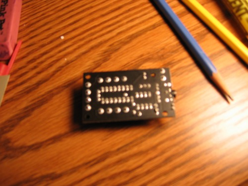
I'm kind of new here so after I failed at just connecting my board, I talked to Chris the Carpenter about it. He couldn't figure out the problem after he reminded me that i needed a jumper cable and it still didn't work. Now, I have some weird little soldering joints on the back that the excess was attaching to other joints on acident I think. Here is a picture that shows where the soldering is attaching in globs to other joint. The joints are between the two prongs at PROG and between the three at the three resistors
Well, there is always desoldering braid from Radio Shack… Very easy to use and you can get rid of the excess solder and try again. If the terminals are just a little stuck together, you can try to gently scrape/ cut them apart with an exacto knife…
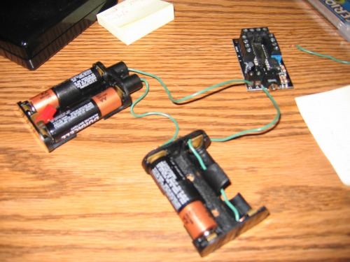
Here is the scoop. I bought a picaxe 8M motorboard, and a serial cable. I hooked it up to 4.5V power and installed the picaxe editor software on my computer. Then I tried to just connect to my board and I kept on getting the connection failed to board error.
When I tried the led test, my board failed to show any voltage between the Prog and 0V.( unless i hooked it up to the wrong 0V terminal).
OK; First: 6V should not be a problem - if so, I would have a lot of problems (Though I tend to use rechargables, that only specs to 1,2V - they often put out much more)
The wiring apart from this looks good IMHO
You have a problem,chosing 8m - the chip on the board is just an 8 - try clicking “Firmware” in “options”, get any response? It should tell you the chip number & make
Do you have other COM ports to chose from in Options?
I don’t get any response in I don’t get any response in firmware, and I tried using com 1 and com 3 but neither of them worked. I am using a serial cord.
The talk about “little soldering joints on the back that the excess was attaching to other joints on acident I think” scares me!
The boards should look perfecty fine, I have never experienced anything else.
And I have never heard of any problems with the setup you have.
Where did you buy this? When things come from Picase, they come with a new manual, (B/W, A5-size). Always very new and nice.
I have tried once - from somewhere else - tried to get a print that someone had been messing with. Aparently it was used, and by mistake gone in the “unused”-bin.
The mods you write about sounds scary - like it is not an original board, or someone messed with it. Can we have a picture of the back of it?
I feel sorry for you that you should have these problems, and with such an easy, steady and simple board this always is…
I bought it from Sparkfun Electronics and it didn’t come with a manual. its hard to tell in the pic, but where the three resisstors are, there is a glob of solder between them. Also there is a small piece where the jumper is on the prog side of the three wires.
I have no experience with Picaxes, but it’s probably safe to say that if there are solder bridges between terminals, they’re a problem (if they wanted to join those two pins, they’d have done it on the PCB itself, not with solder). So I’d try pulling off some of the solder with solder wick, or like they said above, if it’s small enough, you can try and scrape the joint off with a hobby knife.
This thing goes STRAIGHT BACK to Sparkfun Electronics!!!
STRAIGHT!
As a matter of fact, just mail them a link to this very page, and tell them what bad they are doing to their rep - that should make them send you a new board WITH MANUAL right away!!!
I would like to hear if anyone else has recieved boards from Sparkfun - without manuals, or with extra solder on the back, we will show the world!
But for now - let’s just hope they are sorry, mistakes happen, and they ship you a new right away!
I just emailed them that I am going to return it because they like it if you do that when you want to return something. I’ll mail it in tomorrow as soon as they give me the code for the return.
Since they only have 1 left in stock, I think ill just buy the same thing from the other company based in the U.S. and bypass the time it takes for them to get it and ship another back.
Edit: BAH, the other place doesn’t have a picaxe 8 motor board, and I cant find it elsware.
Well, yes two of them are supposed to be hooked together, but the third one is also hooked to them because of excess solder. also there is some between the two prongs at the jumper site


 (Though I tend to use rechargables, that only specs to 1,2V - they often put out much more)
