is a process where two or more cameras can be utilized to determine range or depth of field. The result of the 2 cameras are two slightly different images. Objects are matched in the two pictures and the difference in position relative to each other (horizontal disparity) is used to determine their depth or range from the cameras. If distance between the two cameras is known, simple trigonometric functions can be used to calculate the distance between the cameras and objects in view. Stereopsis is most commonly referred to as depth perception. Sometimes more than two cameras can be used. This is referred to as Multi-View Stereopsis. With more viewers more data can be processed, and the possibility of more accurate distance calculations. Some strategies of determining depth or ranging targets employ moving the viewers to more than one location. Again collecting data from multiple locations can aid in the accuracy of determining depth.
Robotic relevance
Stereopsis can be used in mobile robotics to ovoid obstacles. With the right software inexpensive webcams can be utilized as avoidance sensors or even 3D modeling and mapping. Raw images sent to your robot are not necessarily very useful. The images must be “interpreted” in order to provide useful sensor data. Stereopsis range maps, object recognition, 3D models, are all examples of interpreted or processed data. These are things we do all the time, without even consciously thinking about it, and yet machine vision is a very young field of study.
Natural Examples of Stereo Vision
Many examples can be found in nature of stereo vision. Predators typically have 2 eyes on the same plane, while prey often have eyes on opposite sides of the head. Having eyes on opposite sides of the head provide a much greater field of view. Geese for example can see what is behind them. While cats and owls have eyes one the same plane, which decreases field of view but is better for getting depth, or ranging prey.
If you have ever seen an owl move its head from side to side, the owl is using this process to collect more range information. As it moves its head back and forth, images are collected and processed to create an extremely accurate range map. The owl can use this to determine the exact location of a mouse relative to its current position, which aids in hunting. You can even see people doing it unconsciously.
Try an experiment. Ask someone, "Exactly, how far away is that point" and point to some arbitrary location. Then try to closely observe what they do. Here are some of the actions I have noticed people doing after asking them:
They move their head back and forth slightly (like an owl).
If the object is far enough away they will move their entire body a few steps to the left or right
They will look near their feet and find something they know the length of. Typically they will look at their foot (it's usually easy to find). They will begin counting with an imaginary foot, stacking invisible feet all the way to the target point.
Another interesting fact is infants don’t have depth perception, but develop it within 2 months. I thought this might be the process of their brain developing this faculty. But, I read later that it had more to do with an eye muscle, which is not strong enough at this period to pull and focus the eye inward.
This was very surprising. I thought it was a brain function that figured out the horizontal disparity and that our eyes were parallel. I believe now that we cross our eyes on an object of interest, and the amount that these small muscles flex pulling our eyes together corresponds to the closeness of the object. The brain is an amazing organ, it balances all kinds of disparate information with ease.
There are times when this function does not work. Head trauma can affect this ability to converge images and range distance. Popularized in cartoons, but hopefully not experienced, being hit on the head can produce double vision.
I thought that this might be the brain’s faculties
dealing with trauma. And the reason that we see double is that this is the natural state. Since we have two eyes, we would see the two disparate images if the brain wasn’t constantly trying to correspond and converge everything.
Correspondence Problem
The correspondence problem is the issue of matching the same object in two different pictures. You might think that this problem is trivial to solve. Humans do it near instantaneously and all the time. I found it much more difficult than I expected.
The algorithms I used either were too error prone, or not fast enough to keep up with the video input. Filters can be used to simplify the problem of matching. A little research on the web came up with the following filters and algorithms:
Filters and Algorithms
Software filters and algorithms can be used to process the raw information from the webcams into meaningful information for a robot. Algorithms and filters can assist in edge detection, object recognition, map construction, and ranging.
A Sobel operator can be used for edge detection. Vertical lines extracted from this filter could be used for ranging distance. But the corresponding vertical lines would still need to be found in the left and right views. The Sobel operator uses some matrix math and I have found it a little computationally demanding.
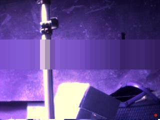
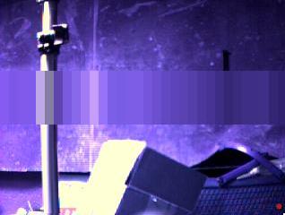
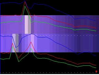
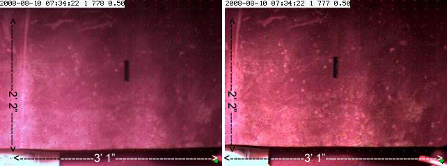
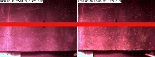
Average filter is the averaging of the pixels within a given area. Here, I chose to use vertical averaging tiles (10 X 60 pixels), because I was much more interested in vertical lines. Vertical lines are of use when the cameras are mounted on a horizontal plane. Vertical lines are used to find the horizontal disparity in stereopsis. Above are two pictures from a left and right camera.
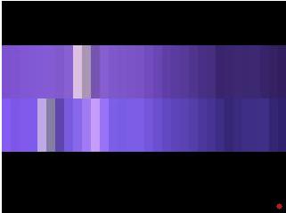
Here the two filtered segments are being compared side by side. A RGB color histogram is superimposed over the average filter segments. You can see how much the cameras vary in color range an luminosity. The horizontal disparity between the camera stand in the two pictures would represent the depth or distance to the stand from the cameras. In order to determine the horizontal disparity, the camera stand must be "matched" in both frames. You may notice a lighter spot on the wall with the right camera's picture. This could create a mismatch depending on what algorithm is used in matching.
Other Visual Queues for Ranging Distance
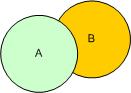
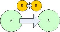
Image Clipping
Object A is in front of object B. We only know this because of the assumed shape/color of Object A and B. Machines and current algorithms do not seem to be very good at “assuming”.
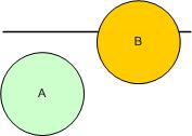
Proximity to Horizon
Object A appears to be in front of object B since object B is closer to the horizon.
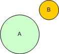
Relative Sizes
If object A and object B are the same type of object, then relative sizes would make object A closer and object B farther away.
Parallax Motion
Object A travels further than object B in the moving frame of view. So, object A is closer than object B. If the camera’s traveling distance is known, the distance to the two objects can be derived using some simple trigonometry.
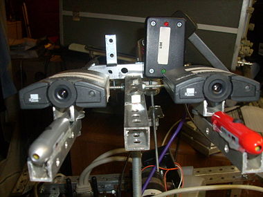
Stereopsis Test 1 “Doing things by hand"
Enough theory already ! Let’s start some experiments !
Defining an area to compare for matching
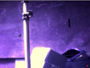
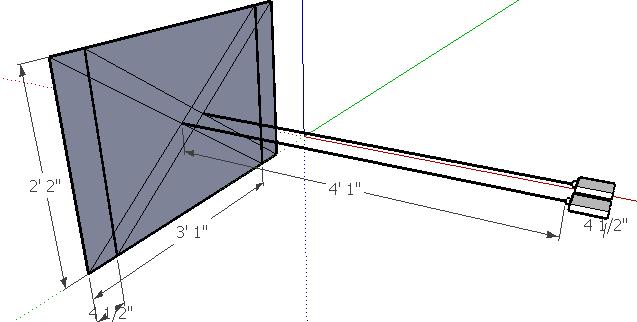
In this simplified view we will go through the steps of an algorithm to find depth using stereopsis. I chose a very simple test to get the first example done. This is a small piece of electrical tape (4” X 1/2") on a relatively plain canvas panel. The canvas panel covers storage area in the basement. Before the experiment, it is good to collect some measurements.
Black Tape 4" X 1/2"
Distance from camera to tape 49"
Field of view of the camera at 49" Horizontal 37", Vertical 26"
Camera pixel width 320
Camera pixel height 240
I captured the two images from each camera and loaded them in Photoshop.
The range/distance of the black line can be derived by the horizontal disparity, the distance of the cameras form one another, and a little trig.
Track VS Match
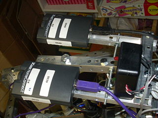
Instead of trying to figure out which object corresponds to which object in two different frames of video, I thought wouldn't be easier to track an object as the camera moved. Then use the parallax effect to estimate range. First, the points of interest in the video frame are found quickly with some very simple algorithms. For example, the first 100 brightest points in a search area. Now if the camera was moved a known amount, the points will move a relative amount proportional to the distance from the camera. I will have to change or build another head for Loki, which has a single camera which can slide to the left and right.
Who knew the Cylons might be right?
I thought the Cylons kept missing the humans with lasers all the time because of their little eye going back and forth. Who knew they were ranging the target? Now it all makes sense.
How far away is your target? "I dunno I'm working on my horizontal disparity map."
I hope that I will be able to create a useful software package which implements a variety of ranging techniques using generic webcams… nothing very useful at the moment, but if your interested I’ll keep you posted…
at the moment using my current software - my bot would be smashing into things … @ 100 lbs - it would mulch my furniture, which is not advantageous for marital bliss
Great write up! That was really interesting. Thanks. You’ve helped un-complicate the complicated for me. It’s something I’ve thought about but was a little intimidated to try. I’ll definately file this in my “clues closet” for future reference!
I certainly have been inspired by you and the folks here, so I was just wanted to share some of the research I was doing… Hopefully, someone will find it useful at some point…
The correspondece problem has been more difficult than I imagined. I think a single oscillating camera might solve a bunch of issues at once and I dont think I’ve seen my imagined design implemented before. Anyway, it should “look cool” … like an egyptian dance move !
So much has changed since I posted this 2+ years ago
The biggest change is I’m using OpenCV as a service and have created a filter mechanism where multiple filters or functions can be attached together.
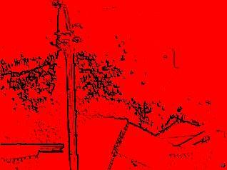
One such filter is inRange - which first converts the image to HSV - (typically this is a more stable color model than RGB)
It then splits the single image into 3 images, one for hue, one for saturation, and one for value. A configurable min and max hue is specified. In addition to a min and max value. At the moment I don’t use saturation, although I could possibly for shadows & highlights.
Anyway, the hue and value images are AND’d together and the result should be a pretty well defined “desired” color area.
I’m pretty sure I could isolate your different shadows…
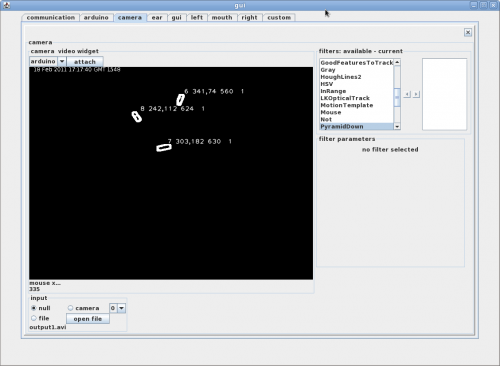
But what do you want to do from there? You could do FindContours - which will find all the unique parts of the resulted filter. It can create a bounding box, and centeroid. You could use the horizontal disparity of centeroids from 2 different filters. However, FindContours can be extremely expensive, depending on the number of contours to find
Also, you have a lovely piece of paper there. Walls, furniture, etc, are usually not so fabulously uniformly reflective.
Matching templates from one filtered template to another would probably be faster than FindContours… but I have not implemented that in a filter (yet)
Pretty cool little gizmo there Gareth. Have you varied the lumens with pwm yet?
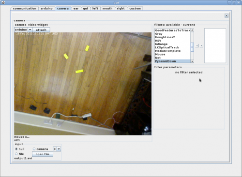
Below is a inRange tweaked for some yellow blocks and the results going to FindContours.
The Mars rover also uses sterio vision for 3D mapping and navigation. It measures the disparity between matching objects from each stereo photo. The greater the disparity, the closer the object is to the rover.