Ok, I completely made my robot, everything working properly, except for my SHARP IR Sensor which i fried, so i ordered a replacement one, I hooked it up following the instructions,put in the batteries and put in the code, and now its working just like my fried sharp did, its looking both directions, and moving backwards (even though im positive it should be set to go forward i even just enter the forward code and it went forwards) no matter whats in front of it (or not in front of it) it does the same thing, also it felt like it was overheating (by the way when i typed in the ADC code it seemed like it was working) so i checked my connections and i found something was plugged in wrong, i plugged it right, (I accidentally plugged the IR sensor in wrong) and tryed testing it, nothing happened so i checked the batteries and there must have been a spark or something because it shocked me (making me move my robot a little and the batteries fell out) so i unplugged everything and plugged everything in and checked every connection and made sure nothing was overheating and put the batteries back in, this time smoke started pouring out from the batteries (or thats at least where it looked like it was coming from) So i took the batteries out, unplugged the SHARP, checked connections, etc. nothing was overheating so i put in the batteries and nothing, the servo didn't even turn, so i used some other rechargeable batteries that i knew had full charge and put them in, still nothing, any ideas to what could be wrong (or fried)??? New Problem
When i plug my robot into my computer and do the readadc command on pin 1, 2, or 3 i get the number 255 when i try it on pin 0 i get a combinations of these numbers: 4, 5, 6, 10, 11, 12, 15, 17, 18, 19 and the combinations switches every 5 seconds no matter if the object it was looking at was stationary for those 5 seconds or if it was moving, but i can see a dim red light in the IR Sensor so i know its working... i've plugged the IR Sensor into every combination of the 3 pins and have done the readadc pin 1, 2, and 3 on every combination of Sharp connections, (the main connection I've been testing on red blue black or V, Vout, gnd) Any ideas as what could be the problem?
Man, I know how you feel. There’s nothing worse than starting all over from the Start Here robot. Makes you feel like your going nowhere…It’s wise to have a spare chip on hand just in case when you Start Here.
Seems to be a short circuit. Check all your solder joints — the 4 connections for the motor on the project board, motor connections, solder joints you have made for the IR on the board, battery case etc.
I guess there is a short circuit between the motor connections on the project board on the bottom side. The 4 motor solder points from the L293D are very close to each other.
Are you sure it shocked you? AA Batteries can produce spaks and make things overheat but they definitely can’t shock you. My guess is you fried the servo and the Sharp. If I were you, I’d take the robot apart and pray the Picaxe isn’t dead. As for what caused the problem, it could be anything from a big nasty short to a faulty Picaxe.
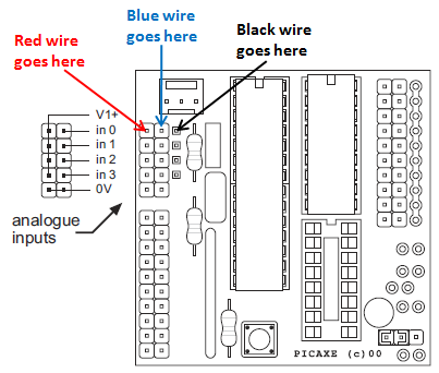
Judging from the picture you have shorted V1+ and 0V (GND) with a shorting block. I mean those pin headers that are used to select between 1 or 2 power supplies. This means you shorted your batteries and that’s why it’s smoking. (I’m kinda wondering why did they put that 0V there anyway.) Move the shorting block to its correct place (the other 2 pins). Check 28-pin project board manual (AXE020.pdf) or pictures of Start Here Bot if you are unsure how it should be.
Also, your Sharp is still hooked up the wrong way. Your Sharp’s GND is now connected to analogue input 1. It should be connected to 0V (those 2 pins next to analogue inputs and V1+ that are not connected to anything in your picture (see AXE020.pdf)).
edit: Now that I looked at your picture again it looks like you have soldered extra pin for Sharp’s GND (like in SHB). So your Sharp should be fine.
This is just something I have screwed up and is easy to do… The data (signal) pin on the ADC inputs on the 28x board are IN THE MIDDLE! It is not to one side as the outputs are configured. It is Gnd,Data,Vcc NOT Gnd,Vcc,Data
I actually ordered 2 Microcontrollers when i started just in case something like this happened, I put in the good one and tried to see if my computer would even read it, but it isn’t detecting the hardware (it detected the hardware before this)
Well I checked all the connections and nothings touching, the motors are working fine, the IR sensor solder points look fine, as for the battery case, the springs are all bent back (maybe because they were overheated?) so i switched battery cases and tried to see if my computer would read it (it still wont) and now the batteries are overheating, but nothing on the project board even feels the slightest bit hot, could the project boards battery connector have something to do with it?
Well i have an extra Picaxe Microcontroller (which switching them out makes nothing different) and as for the servo, i don’t know how to test to see if its working since my computer gives me the “Hardware Error” and when the batteries are plugged in the servo doesn’t turn, which actually made me think that the capacitor on the project board might have been the cause of the shock, and if so i’m pretty sure that would make all the connections bad (Im not certain though) and maybe that would be the reason why my batteries are now overheating, or maybe it has something to do with the battery connection?
In The Beginning I’ve overheated Sharp sensors for like hours and thought they were dead. They’re actually very durable from the hell I’ve put them through. Here’s what you do. Apply power only to your sensors and look directly into them and you should see a dim red light in one of the lenses. If you do then it’s most likey OK. If you don’t then it’s surely dead and time to toss it. Also, don’t know if this helps but I’ve had some strange experiences with these plastic battery holders which have made me cautious everytime I use them. I would put rechargeables in and they would start overheating and smoking and the battery holder is not even connected to anything. Yes, the batteries were inserted correctly. Then I would try another battery holder and no problems at all. Something with the terminals or wires in these plastic holders go whack sometimes…That’s right I’m blaming the damn battery holder!
I just tried that and my robot works again! except for the IR sensor i just got yesterday… my robot now looks both directions drives backwards stops, and drives forwards no matter whats in front of it…
I see the red light, but when i enter the Start Here code (customized to my motors) it does the same thing no matter whats in front of it, it looks both ways, moves backwards, then moves a little forwards
Now get a ruler and a book. Use the book as a target and position it at various distances from the sensor. Use the ruler to measure these distances. Write down the readings you are getting and the distances they go with. Be sure the debug numbers are increasing and decreasing based on the distance of the target and that they are within reasonable ranges.
Now, based on your new data table of distance numbers, pick a “dangerlevel” distance. Plug this into your main code. See what happens. If there is still a problem, you now know that it is not the sensor or it’s data, it is elsewhere in your code. It could be as simple as a < or a > in your if sharpsensor < or > dangerlevel…
It could be a lot of things. Eliminate what it could be, step-by-step and you will end up with what it is.
when i tell my computer to readadc pin 1 i just get the number 255 when i test it on pin 0 I get number combinations out of these numbers 4,5,6,10,11,12,15, 17,18,19 and it doesn’t seem to change that pattern if i move the book, if the book is in the same place for more than 5 seconds the pattern will change to a different combination of those numbers and if i move the book it just continues whatever pattern it was on, not increasing or decreasing. any idea as to what could be wrong? i can still see the red light (pretty dim though) and i’ve tried doing readadc pin 1, 2, and 3 and i’ve plugged the Sharp Wires into every combination and tried readadc pin 1,2, and 3 on every combination. Does this mean theres a problem with the Sharp IR or what?
Just to make sure: Is your Sharp connected like this (image from AXE020.pdf):
If it's connected like that then you have connected it correctly. Hopefully you haven't fried your Sharp yet by trying "every combination of Sharp connections". I really don't know what would happen if you reverse polarity (mix up red and black wire) or connect Vo (blue wire in your case) to V1+ or 0V. In worst case the Sharp's gonna be fried so don't just plug things in without knowing what you are doing.
Back to your problem:
I assume that your connections are now like they are in this picture (shorting block moved to its correct place of course) and my picture above. If they are then the reason why you are getting 255 from ADC pins 1, 2 and 3 is quite obvious. Just look at picture above and think how you have connected ADC pins 1, 2 and 3. Right, you have connected then to V1+. What does that mean? It means Analogue to Digital Converter (ADC) sees V1+ in all those pins. Because Picaxe's ADC measures voltage between 0V and V1+ it means that ADC sees the maximum voltage and that means readadc will give the maximum value (255).
I didn't notice you telling what Sharp sensor you have. I'm guessing it's either GP2D12 or GP2D120. GP2D12 has measuring distance ranging from 10cm to 80cm and GP2D120 has measuring distance ranging from 4cm to 30cm. When you were testing your sensor did you have you obstacle (book) within the range? Also, did you know that the value you get from readadc will get BIGGER when the obstacle is CLOSER when using these sensors? You can figure that out if you understand how ADC works and read the Sharp sensors datasheet (for example here for GP2D12 and here for GP2D120).
Now, if you are sure your connections are correct try your sensor once again with the code Chris posted earlier. Place the obstacle (book or whatever) 10cm away from the sensor. What values are you getting from the sensor? If you move the obstacle placing it 15cm away from the sensor what values are you getting now? Try other distances too and make sure the distance is within acceptable range. Just don't touch or move anything when you are reading the values.
I have a GP2D12 I have it connected just like the picture above, I can still see a faint red light in the Sharps Eye, but as for the distance results all of them are combination of 1 through 12 Here are the results anyway: 10 cm = 1,2,4,5,6,7,8,9,10,11,12 15 cm = 2,3,5,6,7,9,10,11,12 30 cm = 1,3,5,6,7,8,10,12 and when i moved it back to 10 cm from 30 cm the results changed (but the numbers where still in the 1-12 range) Do you think i fried it even though the red lights still on? thanks for all the help!
If I had to guess I’d say your Sharp’s fried. You can test your Sharp with a multimeter if you want. Just power the Sharp directly from batteries and measure the voltage between Sharp’s Vo and GND. When you move an object in front of the sensor the voltage should follow the curve given in the datasheet (page 4). Just be careful not to short circuit anything if you go ahead and test your sensor this way.
Another possibility could be that Picaxe’s ADC is faulty/fried but I don’t really think that’s the case here. You can test that too if you have an extra potentiometer lying around. Connect potentiometer’s center pin to Picaxe’s analogue input, potentiometer’s left pin to V1+ and potentiometer’s right pin to 0V. Using the test code poster earlier you should get values between 0 and 255 when you turn the potentiometer.
That’s all I can think of right now. I’m out of ideas.
What’s Up! You’ve been at this for a while. If your sensors measurements are not correct then something may be wrong but I don’t think you fried the sensors so don’t toss them so quickly. You can contact Acroname and they’ll provide some support regarding all the Sharp models. They have been promoting the Sharp sensors for a while now and think they even had a troubleshooting guide once so give them a ring and see what they say regarding your situation. Location: USA
I know one thing you’re not suppose to do and that is turn or loosen that screw located on the back of the sensor which would affect the calibration if I remember correctly.
Also, I’ve had enough of you, and the Start Here Robot and the guy who wrote the code is Nuts.
Just Kidding Sometimes. If you send me your home address to [email protected] I will mail you a working sensor to test. I have one GP2D12 that won’t go to use because I failed on the Start Here robot. It was just too advanced for me and the guy who wrote the code is Nuts. Did I mention that the guy who wrote the code is Nuts? Anyway, if you get it working then your one step closer to a dangerously clean navigation code using the SRF05 written by the same guy who is Nuts…
If you can tell I’m angry it’s because I wanted to Start Here just as much as you but I didn’t have the brains Man!

