Ok, here's my problem for you guys. How do you use a MCU(Arduino, PIC, Stamp, etc) to detect if the bot has a motor stalled on it. I know it can be done, because I've read about bots that are bumperless and detect which motor(s) are stalled for collision detection. Yes, I know you measure the amps that the motor is pulling, but how do you use the microcontroller to do it?
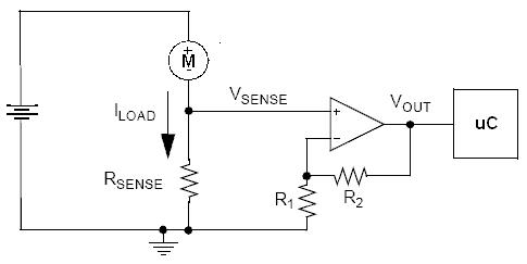
I just use a shunt/sense resistor, like this (I don’t even use the op amp cause I don’t need full resolution):
But remember it's a bit more complicated with DC motors cause they change direction = poles...
UPDATE: BTW I recommend using the Serial Oscilloscope I made recently when studying/plotting the current draw patterns. The processing based one I started out with performs awfully.
Stalled Motor I have seen people make an encoder ring, alternating white/black segments and attach to a wheel. Then use a #QRB1114 IR transceiver to send signals to processor chip. A steady on or off signal for more than .xx seconds (depends on speed of your wheel and number of encoder lines) would signal a stalled motor.
I’ll have the sensors in next week, I hope then the wheels can be encoded. Encoding will be the hardware part of the solution and adding a few lines of code to check the last known tick against the current reading of the timer, and checking if the motor is supposed to be turning or not. Just a few variables to plug in. I know there is never an easy fix, but was hoping somebody had already came across it and had a solution for it.
Just thought this might be of interest to you. I recently put together a homemade wheel encoder. Check it out and off course you’re welcome to ask questions…
Way cool! Looks awesome, mine will be encoded, but going to use hall effect sensors to do it with. I got the idea from looking at tachometer circuits. It’s not as precise as what you did, but it will work I think. I know it will be fun though, figure if nothing else I will have figured out a way to not do it.