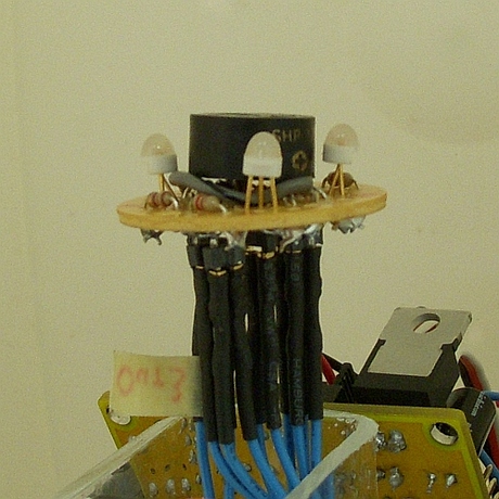
SoundnFury is a small electronics module with a piezo speaker and four red-green LEDs installed on a round Radio Shack circuit board.
SoundnFury provides a compact way to add LEDs and sound to a small robot. One digital output is needed for the piezo speaker, and two outputs each are needed for the LEDs. The LED ground connection is shared.
I am currently using SoundnFury on Why Tri, which you can see in the posted video. I have four of the LEDs connected to PWM outputs of the uBotino board for Why Tri. This will let me do some cool fading effects. I will post some suggested code for the module soon, but I'll bet many of you could come up with even better things to do with it.
https://www.youtube.com/watch?v=z45QFEcEoOE
Nice LEDs
Were did you get those neat LEDs?
I got them from the
I got them from the Electronic Goldmine here.
Vendor’s Description:
Red/Green-Yellow T1 Bipolar LED - Diffused white lens with Standard brightness. NOTE: The third color shown (-) is produced when both LED chips flash on at the same time. Package of 5.
I think the ‘Yellow’ color is more like orange. The LEDs have a nice diffused lens that is fairly visible from the side, which is one of the reasons I picked them for this project.
RGB
Sort of like a RGB LED but a RG LED.
Wow those LEDs really are
Wow those LEDs really are awesome! Thanks for sharing!
Nice one IG! I am curious
Nice one IG! I am curious what pins did you use for the LEDs? 4 PWM pins, that are 3,9,10,11? What about the servo, did you use the Servo lib (I guess not, since it voids the PWM signal on pins 9 and 10…)?
Cheers!
Let’s see here. I wanted to
Let’s see here. I wanted to use as many PWM pins as I could. I grabbed four, as mapped below, and put two on green and two on red to spread out the effects.
#define LED1_Red 2 // digital pin 2 - Front Left LED
#define LED1_Green 3 // digital pin 3 (pwm)
#define LED2_Red 9 // digital pin 9 (pwm) - Front Right LED
#define LED2_Green 1 // digital pin 1
#define LED3_Red 12 // digital pin 12 - Rear Right LED
#define LED3_Green 11 // digital pin 11 (pwm)
#define LED4_Red 10 // digital pin 10 (pwm) - Rear Left LED
#define LED4_Green 0 // digital pin 0
#define piezo 4 // digital pin 4
I’m currently using the standard Servo library, as I only have one servo!
You know that the Servo
You know that the Servo library uses Timer1 and prevents the user from using analogWrite on pins 9 and 10, right? I would use the SoftwareServo library that has no restrictions, especially because you’re using only one servo.
I guess that because you’re using LEDs on the serial pins you have no problems uploading code, they will just flicker a bit. Other serial devices have to be removed or you’ll get an error and the code won’t upload.
Thanks for that info. I’ll
Thanks for that info. I’ll have to adjust my code for the SoftwareServo library.
As long as I’m not using the Serial Monitor, and I set digital pin 0 low in setup, I don’t get any flicker. I haven’t had any trouble uploading code. I guess the LED and limiting resistor aren’t enough to bother the serial line. I do indeed get a flicker on the LEDs on digital pins 0 and 1 during upload, but it’s no problem.


