Solar charger for multiple batteries

Hi everyone,

I couldn't decide which forum topic to use for my post so I'll post right here in the "Absolute beginners" because I'm actually a programmer and I'm quite new to electronics so I don't want to put expectations too high. I may do or say something that looks pretty stupid for an experienced robot builder so forgive me and don't hesitate to mention it if it happen, I'm here to learn.

Now that I'm done with the presentation part, here is my multipart question.

I managed to build some kind of Solar Li-Po charger using a tutorial and stuff I bought at Adafruit.

The idea came from this tutorial when I wanted to power a Raspberry PI from Solar Panels:
https://blog.adafruit.com/2014/06/20/how-to-build-a-solar-powered-raspberry-pi-piday-raspberrypi-raspberry_pi/

But I decided that I would go with better product than what was suggested in the tutorial:

So I bought a "Huge 6V 5.6W Solar panel" instead of the Medium one because I thought that a smaller panel might not be enough to sustain the power needed by a Raspberry PI, and I bought a PowerBoost 1000 voltage regulator instead of a Powerboost 500 because I thought that 500ma was somewhat limited.

Here is my setup:

Free Energy! :o)
(Well not free because it's powered by my desk lamp right now but you get the point)

The solar panel (upper right) goes into the LiPo charger, which charge the Battery (left) plugged in the "batt" connector. The "Load" connector goes into the PowerBoost 1000 which upscale the Voltage from 3.7V to 5V to power my Arduino via a USB cable. And I also added connection to a breadboard that isn't upscaled so my Arduino could theorically check the battery voltage too using this connection.

Everything is working BUT I know (think?) that upscaling is less efficient than downscaling voltage and, if I want to power a Rover with 7.4V, I will need two LiPo connected together. (In serie)

That's where I'm kind of stuck. Serial charging seems to be a lot harder to do. (That or there are not a lot of samples on the net about this)

After some googling, I found that there actually IS a way to do it according to this adafruit document which involve a 3PDT switch but that's less than practical because it involve disconnecting the load each time you want to charge. (If it's solar powered all the time and my Arduino or Rasp-Pi need to monitor the charge without losing power, that's a big no...)


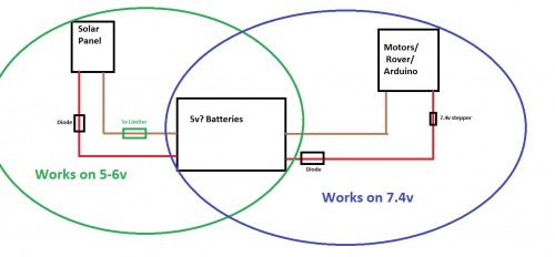
Now the only way I think that could work is to have two battery banks (4 batteries in total) using the solution above. While one set of batteries is solar-charging, the second set power the microcontroller and, when charging is complete, I should quickly switch power (using a big capacitor on the Load to avoid a quick blackout) between the first and second set. At time time, the first set will be connected to LOAD instead of charging while the second set will be charging instead of powering the circuit. This also has the advantage that the batteries will be in parallel while charging so they will be equalised frequently meaning less risk of dangerous LiPo fire.

That could work but, I mean, laptops do it all the time. They can charge and be used at the same time while using multiple batteries in serial. That look like trivial. How do they do it? Is my idea a good one or am I going in the wrong direction? Is there anything else I missed or maybe someone has another idea that could work?

Thanks for your feedback!

Batteries can indeed be

Batteries can indeed be discharged while charging, if you want to isolate circuits use diodes.

Yes they can

Sure they can, I did it with a single LiPO battery without problem. :slight_smile: The problem arise the moment I need more voltage and have more than one battery in serie. And I don’t want to charge them in serie at 7.4V because they could be in different charge state and that could be dangerous to overcharge one of them. I therefore need to charge them in parallel (which the 3PDT switch is for) so they can equalize. But the problem I have is that they can’t power the load in that “charging” state.

I don’t know if I correctly stated the problem in my post. Sorry if my goal here is not crystal clear.

I also read about another strategy. But wow, that could grow complicated quickly.

I’m also a Nissan Leaf owner so I read a bit about how the battery pack to try to understand how it work. I may be off track but if I understood correctly, it seems that the batteries are charged in serie (360V). The way the software equalise the battery is that if any cell voltage is too high, it will drain (bleed?) that cell by switching ON a resistor to reduce it’s state of charge. That allow the car to charge the pack (and equalize) while being able to use the pack at the same time. That may be another possibility but I would need a 7.4V solar charger circuit which I haven’t found yet. (If that’s really how it work, I can’t imagine the complexity of my car’s battery pack to allow it to mesure SOC and equalize 192 individual cells.)

I really like to experiment a lot of stuff but the batteries are the only part I really don’t want to screw up because of all those LiPO fire video I saw :wink: I would like to build some kind of battery module that can handle what I want to throw at it (like solar charging while in use), make sure it’s 100% safe, and simply replicate the module for all my future projects so I can focus on other things. (Things I’m not afraid to mess up)
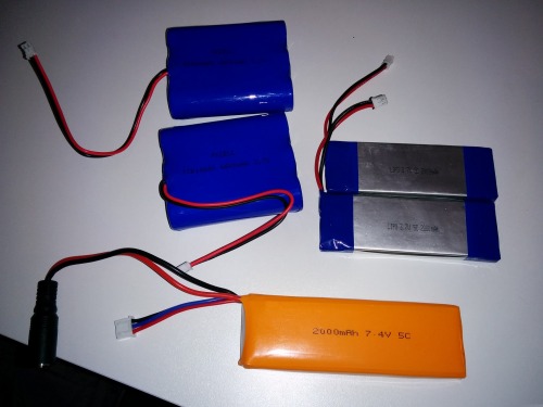
I’m just going to answer

I’m just going to answer this the best I understand of your asking.
I started as a programmer too, so figure you might not know this, like I didn’t.

For start, just a friendly correction, it’s called a “series” circuit, because all the devices are in a series.
A parallel circuit is because the lines theoritically run in parallel across the devices in that circuit.
(I just saw it multiple times, so figured it wasn’t a typo)

Power sources in a series circuit circuit increases voltage, while in a parallel circuit increases their amerage.
(Just in case you didn’t know, because it’s related)

I think maybe we’re confused because we’re not sure what you’re asking.
It’s my understand you’ve already built a functioning solar charger that recharges the batteries and runs the Arduino, right? Also, if I’m understanding correctly, the only reason you’re wanting to modify it is because you need more voltage to build up on your project?

The power you’ll need is about wattage in general. I had issues with a project for months not understanding this. XD
Any voltage conversion has a conversion rate that makes it lose some power in the process. Maybe the reason you believe stepping voltage up is less effecient is because of those rates, but I don’t know this to be true: I have a 12v -> 5v converter which has only about 80% effeciency. Your converter claims 90%+ effeciency.

Your solar panel output is 5.6w, which would be about 1.07%, minus 10% or less, would leave you with possibly 970mA at 5v.
We don’t know how much power your Arduino is taking, plus whatever else you have running.

You want to charge your batteries in parellel and use them in series, but I think Silux has the answer you want. You would keep them series. You could put a voltage limiter on a diode from the Solar Panel to the batteries, charging them at 5v (or whatever you set). Then on ANOTHER diode, to the rover/motors, put the voltage stepper to get your 7.4v from the batteries and solar panel.

I’m just not sure it will work very well for you. Here’s why:
The reason you’d normally be switching between charging and using the device is because how much power is used. Different require different amps, depending on how good they are. IIRC, the Rover has 6 motors, and I’ll assume a steering servo. While the Arduino is probably pretty power effecient, those motors plus any electronics, like your power monitoring, could take more than you expect. You probably wouldn’t get much life out of those 5v batteries. You didn’t say what their mAh was, but what I use is rated at 50Ah at 3v, which conversion gets much less; so I use one for the main device and one for the motors. 

If you want a more effecient way, get better batteries for your job. 
While you may have to place things around, and I’m still learning some electrical stuff, so I may be overlooking something, I made a visual for an idea (again, if I’m understanding what you want correctly). 

Another programmer :slight_smile:

Great! I know I may say something that sound silly but don’t hesitate to correct me, I’m here to learn. Also can you make bigger version of your image? It’s so small I can’t read what you wrote on it.

And yes I was talking about having multiple power source (batteries) in serie. So 2 x 3.4V become 7.4V with same mAh. I’m sorry if I ever mentionned “serie circuit”.

I have 5 power packs on hand right now.


IMG_20151007_204609.jpg


  • 2 x 3.7V LiPo with 2000 mAaH (7.4 Wh each?)
  • 2 x 3.7V LiPo with 6600 mAh (Bigger blue packs) (24.42 Wh each?)
  • 1 x 7.4V LiPo @ 2000 mAh (14.8 Wh?)

Maybe one will work better than the others for what I intend to do.

I have built a Rover. (Funny I received your answer as I was in the process of video editing to create my first robot post on LMR) Initially, I was using only one 3.7V battery and I was stepping voltage up for the Raspberry PI I used. But I also connected the battery right into the motor controller to power to motors. (No voltage regulator) The motor didn’t go as fast as I would like so that’s why I upgraded my design to use 7.4V instead. So now I feed 7.4V to the motor controller (still no voltage regulator) while I step down to 5V for the Raspberry PI as well as two servo I added to pan & tilt a camera. It work fine. Except I can’t charge a 7.4V battery with a 6V solar panel :wink:

So let see if I understand. What I think you’re telling me is:

  • Even if I use two batteries, I should put them in parallel (power source stays at 3.7V but increase in mAh) so my solar panel work as it is. -> I’m fine with that why not :wink:
  • I could put a voltage limiter on a diode from the Solar Panel to the batteries. -> I really don’t know about voltage limiter. I may have to google that. But I think my solar charger circuit already have a diode built-in so power won’t flow in opposite direction and it will also stop charging when my batteries are full. Does that mean I don’t need the voltage limiter diode?
  • I should use a step-up voltage regulator to power my motors. -> Wow, I don’t know why I never tought of that solution. I assumed that amp requirement would be too big for the regulator and cause a brownout
  • I should use a diode between the Voltage Regulator and the motors. -> I’m not sure about the reason behind this diode. How can the current flow backward at this point since the Rover do not generate power? Because of motor interferences?

I think I will try to finish my Rover robot post so maybe this question will be easier to understand. I’ll post the url back here when it’s done.

Thanks Reidmere! (And Silux)

My first Robot project

Here it is:

https://www.robotshop.com/letsmakerobots/wifi-controlled-raspberry-pi-2-rover

This is the link to my first robot project.

The reason for the green

The reason for the green limiter would be to prevent the return voltage from the motor circuit from perhaps making parellel and going to the solar panel, perhaps damaging it. I don’t know for sure that’s an issue to be concerned with, but I’d do it for safety’s sake.

The reason for the circules is to show the batteries would be on two different circuits… though theorietically, the solar panels would be tied to the motors, passing parellel to the 7.4 voltage converter. Meaning, your rover would run of it and the batteries, whichever voltage is higher first. When the motors are not running, the solar panel will only power the batteries.

Just make sure you’re still wiring the batteries proper to be on both circuits, which it’s my understanding you already have; I’m just saying don’t change that. ;) 


rover2.jpg

As an afterthought, I

As an afterthought, I realized depending on regulator, the return line to the motor will probably be going to the regulator…

If it does, you do not need to voltage limit your line. In fact, if it doesn’t, you need to voltage limit the return line.
That sketch was just something a threw together for you for what I was loosely visualizing… but basically that brown line on the left would go to the limiter, then to the batteries, giving the batteries the 5v (or whatever v) you need the batteries at.

You’d probably not need the diode on the right then either, the image was just for the concept, which I think you already understand. :slight_smile:

voltage monitoring

LiPo needs voltage monitoring to be charged properly, and cell balancing becomes a necessity after some cycles, to avoid cells dying or overcharge.

What you need is a balancer circuit. Search in R/C communities.

12 V

It seeems to me you have some money to throw at this, so…

I think you will have trouble running these LiPo’s in series and then charging them that way.

I suggest you get another 6V solar panel and run both panels in series, there are some issue here to but easier to work around. Use that to charge an old school deep cycle 12V lead acid battery, small is fine.

Use that 12V battery to run a smart LiPo charger like this:

http://www.ebay.com/itm/252047704675?_trksid=p2057872.m2749.l2649&ssPageName=STRK%3AMEBIDX%3AIT

Then if you need 7.4V, just buy a 2S (7.4V) LiPo battery that has the cells internally matched. That type charger will charge just about whatever LiPo batteries you have an keep  them up. Anything that needs to run continuously can just run off that deep cycle.


Nice!

I think that’s actually a very good idea. Maybe not for a rover because of Lead acid battery weight but for a stationnary project that is a great idea! (But again, there seems to be some small form factor lead acid batteries out there: http://www.zbattery.com/Universal-12V-0-8Ah-Sealed-Lead-Acid-Battery?sc=2&category=62965

That way I could not fear any LiPo battery problem since the the LiPo charger will take good care of the batteries. (As long as I don’t let them die.) And I could check for the 12V battery voltage with an Analog-in wire and install a relay to be able to stop the LiPo charger before my 12V battery gets too low. And another analog-in wire would make sure the LiPo doesn’t gets too low. In that case, the software should disconnect the whole circuit as a fail-safe.

I think that this idea has some real potential.

Thanks!

:slight_smile:

I will definitely try that.

Thanks!

Make hay while the sun shines

Your welcome.

Note also that if you set up  this way, you’ll be able to recharge your LiPo anytime, not just while the sun is shining. And, you’ll be able to store sunshine as electricity even when you don’t need to recharge a LiPo.

I have some interest in solar. Although everything I have done is on the thermal side, I am aware of much of the technology and resources of the PV (photovoltaic) side.

There are a few low price distributors in south Florida, serving mostly Central and South America, I believe. Here is one (although not the one I was looking for):

http://sunelec.com/

Prices have really come down.


Battery charging chip… :slight_smile:

Like Silux said, you should use a balancing circuit. You may want to have a look at what TI has to offer (samples! :stuck_out_tongue: ) here, like this chip. Some of those chips can both handle charging the batteries and power a load at the same time, automatically managing both tasks! :slight_smile: