


I recently got in a few parts to complete my smd soldering station and I would like to share my experience along with you. I found that I have started wanting smaller and smaller control boards as well as lighter ones so I turned to smd components and boards. Below is a guide to help you get started in smd soldering with many tips and tricks as well as what you will need.
What you need
- Erem 4.75" Tweezers 578-EROPOOSA Mouser part # or equivalent
- Sticky tack local store
- 60/40 solder small dia .025
- Rosin flux pen 2113092 Jameco part number
- Smd componets bulk x100 at Mouser or Jameco
- Plastic bins for parts
- Desoldering braid not shown in the picture
- Isopropyl alcohol 91%
- Acid brushes bulk 100 packs are cheap
- Mini vise 134439 Jameco part number
- Solder station

Perpare the work area by clearing away everything as it is easy to lose a smd part if your not careful

First lets find a circuit for this circiut lets start with something easy and useful I chose a 555 timer servo controller

Step one - mount proto board in vise and use flux pen on the soic chip area, you will need to press the tip down on a solid surface to get the flux running if its the first time using it.

Step two - Place a small dab of sticky tack on the top of the pcb where the 555 timer will be placed. Then carefuly position the IC on the surface andline the pins with the traces.


Step three - Now solder the IC in place. If you use too much or make a solder bridge like I did do not worry will will fix it next step.
Step four - Using the Desouldering braid remove excess solder from the chip leaving very little. Now take a acid brush and trim the brush hairs off at a angle to add strength to them. Dip in alcohol and clean the connections as well as the chip itself.


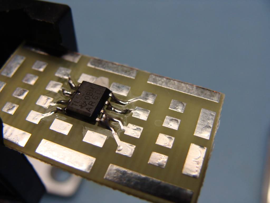
Bellow is the end result, You now have soldered your first smd part \o/

Now repeat steps one though four for the next remaining componets

Dont forget power and the enable line for the 555 timer!!

I finished the board and found that I did not hook up V+ to the enable line so in the video the circiut was acting up though you can see the end Item working.
http://s155.photobucket.com/albums/s291/ollopat/?action=view¤t=MOV03641.mp4
I added a light sensor so that I could contol the servo. You can use many other anolog sensors like a IR or a bend sensor. This same circuit doubled will make a anolog 556 controled wall following robot as well which Im in the process of making with smd parts.

If you have any questions dont be afraid to ask
DoCDoC
