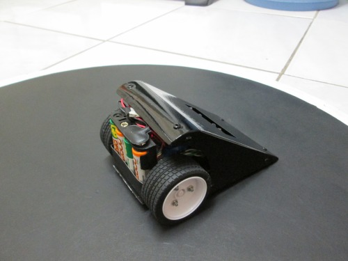
I saw a video clip of a mini sumo bot a while ago and set out on a mission to build one for my 5 year old son. Being my first robot, it turned out to be quite a challange and after a lot of struggling and tons of fun it's finally working.
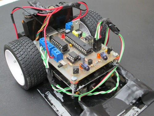
I started with the circuit design which basically consists of the following:
1 x 18f2550 loaded with a modified usb boot loader
2 x L293D motor controllers, piggy backed to handle the load
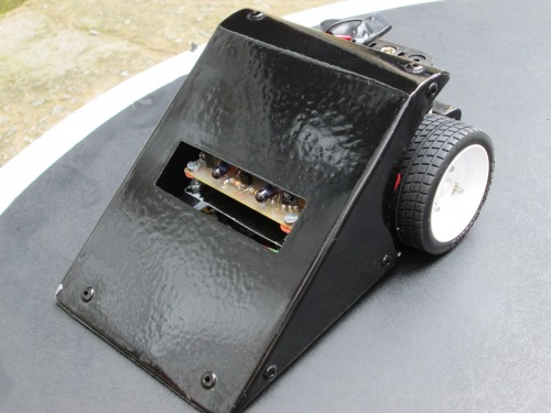
2 x CNY70 optical sensors to detect the line
2 x IR Led and IR remote reciever to detect the opponent.
I couldn't figure out how to generate the 38khz signal required for the reciever seen as the pwm ports where being used to control the motors so I ended up using a 555 timer to generate the 38khz carrier with the processor enabling and disabling the 555 in order to generate the IR bursts.
My next step was to design the board using the free version of Eagle CAD and one of my work colleagues etched the board using a homemade UV box and ferric chloride.
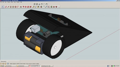
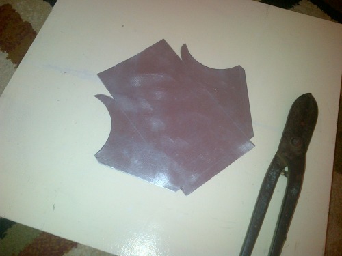
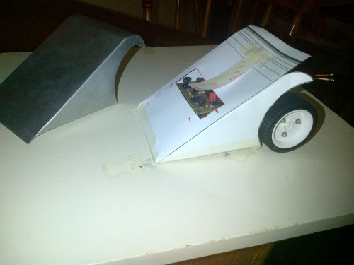
I used Sketchup to design the template for my chassis and made it out of an old piece of sheet steel I found lying around.
Sourcing decent motors turned out to be an issue due to financial and logistical constraints and I ended up using an old Tamiya gearbox which my work colleague generously donated to the project. Thanks Charles!
The code uses a simple FSM. There are 3 states - Hunt, Attack & Survive. I compiled the code using MPLAB IDE v8.88 and the C18 compiler.
All in all I'm pretty happy with the outcome, the dimensions don't conform 100% to the mini sumo rules (this was mainly due to the size of the gearbox and the width of the wheels) but there aren't any mini sumo competitions in my country so it's not an issue.
Anyways, thanks for taking a look at my project. I'll post a video soon.
If you ever consider trying to drive the LEDs at 38kHz, you might want to look at projects that do something like software PWM and maybe read the tutorial that LadyAda put up about generating a 38kHz frequency on an arduino to send Sony IR codes.
It’s a shame you don’t have a competition to put it in because it looks like it could be a good competitor. Offloading the ir to a 555 is probably a good thing anyway as you should have more processing time available instead of including a bit banged 38khz signal in your main loop.
I wonder though if the ir leds and receivers wouldn’t be vulnerable to damage from some other bots if it were to compete. Perhaps a clear window over them for protection? Of course anything you used wouldn’t want to reflect any ir light back or you’d get false readings.
Any chance you could put the code up in your post?
Thanks for all the comments, should have posted my progress here a while ago, probably would have saved me a lot of time.
I’ve added a small video clip, it’s my sons bot so I had to make it interesting, the toys are fine but the 1/2kg can took a bit of a knock Will post my code soon, I patched it together from code that others had shared so really don’t mind.
Hello sir, can you tell me if carl0sgs’s ir line sensor will work for this robot, here is the link:http://www.thingiverse.com/thing:26819 big thank you to both of you sirs :).
About the IR line sensors Hi, carl0sgs’s ir line sensor will work perfectly. I only used 2 line sensors so you could either use the two outer sensors or make a minor code change in order to use the spare ports RA2 and RA3
That’s correct, use the pin That’s correct, use the pin headers connected to RA0 and RA1. The only value that may need to be tweaked is the line_threshold in main.h as the output voltage of the circuit will vary depending on the height of the sensor from the surface as well as the reflectance of the surface. By adjusting this value in the code you can ensure that the robot clearly distinguishes between a black and white surface.
But i don’t know how to do that :), i have never build something with a pic mcu, so can you give me your schematic for the line senors, i only know arduino programming and electronics, i’m not very familiar with the pic microcontroller programming. Thank you.
PS. I have made a pickit2 clone. How do i upload the code, will it work when i just upload the smash n dash hex to the pic with the programmer or i have to burn the bootloader for the compiler and with the compiler upload the .c file ?.
Ian’s been gracious enough to supply the whole project directory. All you need to do is open it in mplab, build it and upload it to your pic. Make sure your using the same pic as Ian or you will have to change the code to suit yours. That may be a bigger task than worthwhile and easier to just start from scratch, depending on which partnumber.
If you have a pickit2 clone you do not need a bootloader to upload code. In mplab you select pickit2 under programmer in the menu. If your programmer works it should tell you it’s connected in the output window. Usually the output window is open by default but if it is closed you can open it under the view menu. It may give you an error message if the pic is not connected to the programmer. Also depending on how your pic is installed for programming. I mean if it has it’s own power supply or not, you may have to select power from pickit2 to program it.
I don’t know anything about the schematic. You asked a programming question and I answered it. You have to focus on one problem at a time. If you change from one to the other without solving the first you will never solve anything.
The carl0sgs’s ir line sensor is identical to the schematic I used, just connect the two output wires to RA0 and RA1. You will see that the board has 3 strips of pin headers, the outer strip can be used to supply 5v to the sensors and the centre strip will be used for gnd the inner strip connects to the the processor pins. Use the two pins that connect to RA0 (left sensor) and RA1 (right sensor)
Hi, I have attached the schematic I used. Could you explain the issues you are experiencing with the line sensors?
The line sensor circuit can be tested before connecting it to the board by connecting a multimeter between the output and ground and measuring the dc voltage while holding the sensor ±6mm above a black and white surface. The voltage should be higher over a white surface due to the increased reflectance.
When the circuit is connected to the board the processor will convert the voltage to a value between 0 and 255.
The smashndash.c code checks to see if the value is higher than the LINE_THRESHOLD value
if ((LineL>LINE_THRESHOLD)||(LineR>LINE_THRESHOLD)) { currentState = SURVIVE;}
The line_threshhold value is set to 100 in the main.h file
#define LINE_THRESHOLD 100
If the sensor is too close to the surface you may exceed the value of 100 on a black surface which would make the robot think it’s on a white surface and enter the survive state. This issue can be resolved by either raising the sensor or increasing the LINE_THRESHOLD value using a text editor (i prefer Notepad++ because I can set the language to C and the color makes the code more legible).
Once the value has been edited you can re-compile the code by downloading and installing MPLAB IDE v8.92 and MPLAB C for PIC18 v3.46 in LITE mode (MPLAB C18) ,opening the project by double clicking smashndash.mcp and pressing F10 to compile.
Hi, I have attached a copy of the bootloader software. Upload the bootloader hex file using the pickit2. Once the bootloader has been uploaded you can connect the board via USB and run the the HIDBootloader.exe application. Enter bootload mode by pressing and holding the RUN button while turning the board ON. The hearbeat LED should start blinking. Click Load Hex File and then navigate to the smash n dash HEX file you want to program. Click Program/Verify and reset the board once the programming is complete.