Ok so I went online to finish buying all the parts that I want and came across a few extra sensors I liked along the way. 
Updated parts list
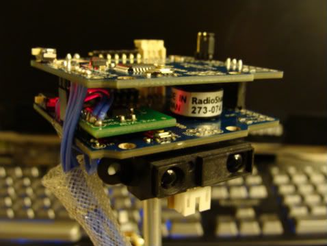
3 Hitec HS-475HB (76 oz. in.) Standard Servo’s; two modified for continuous rotation
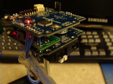
2 Arduino’s Pro found at www.sparkfun.com
1 FTDI FT232RL USB to program the microprocessors
1 Logic Level Converter for 5v to 3.3v
1 ADXL330 Accelerometer
2 GP2D12 IR Sensors
1 Servo Tire and Wheel - 2.63" x 0.35" (pair) found at www.lynxmotion.com
1 line “Tracker Sensor” also found at www.lynxmotion.com
1 MLX90614 Infra Red Thermometer Module (90° FOV) (Cant wait for this one to get here ) found at www.parallax.com
1 Ping))) sensor ultrasonic sensor also found at www.parallax.com
1 ServoPAL (think really small 2 servo controler) also found at www.parallax.com
1 5v PsP Backup Battery
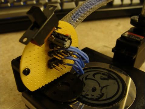
1 Small piece of acrylic
1 small Castor
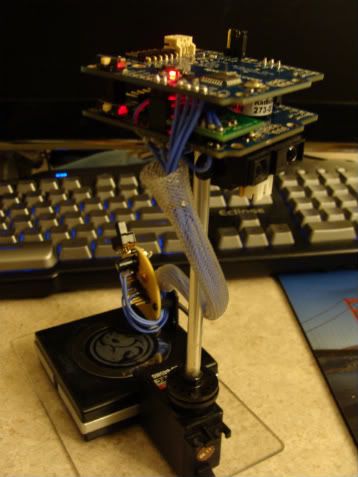
1 metal tube
1 small breadboard
Sorry no pics yet still waiting on all the parts to arrive…
But never fear I have a new section of code for reading the Infra Red Thermometer 8)
This simple code uses Peter Fleurys libray here:
homepage.hispeed.ch/peterfleury/ … tware.html
Scroll down and download the i2c master libraries. Create a folder in /{arduino root}/hardware/libraries and copy the
(i2cmaster.h and twimaster.c).
You need to change the .c file to .cpp (otherwise it won’t link when compiling) and don’t forget to change some of the values
in the .h and .c file depending on your mcu etc.
Hehe the original coding I found only converted to degrees C so I added a line for degrees F
[code]//Simple program to read data from the MLX90614 infra Red Therm sensor convert from degrees
//kelvin to degrees C then degress F and print to serial port.
#include <i2cmaster.h>
void setup()
{
Serial.begin(9600);
i2c_init(); //Initialise the i2c bus
}
void loop()
{
int dev = 0x5A<<1; //Address must be bit shifted left, library does not automatically do it
int data_low = 0;
int data_high = 0;
int pec = 0;
i2c_start_wait(dev+I2C_WRITE); //send start condition and write bit
i2c_write(0x07); //send command for device to action
i2c_rep_start(dev+I2C_READ); //send repeated start condition, device will ack
data_low = i2c_readAck(); //Read 1 byte and then send ack
data_high = i2c_readAck(); //Read 1 byte and then send ack
pec = i2c_readNak(); //Read error check byte and send Nack to tell device no more data to send
i2c_stop(); //Release bus, end transaction
//This converts high and low bytes together and processes temperature, MSB is a error bit and is ignored for temps
double tempFactor = 0.02; // 0.02 degrees per LSB
int tempData = 0x0000;
// This masks off the error bit of the high byte, then moves it left 8 bits and adds the low byte.
tempData = (int)(((data_high & 0x007F) << 8) + data_low);
tempData = (tempData * tempFactor)-0.01;
tempData = tempData - 273.15; // Convert Kelvin to Celcius
tempData = (tempData * 9.0)/ 5.0 + 32.0; // Convert Celcius to Fahrenheit
Serial.println(tempData); //Print temp in degrees F to serial
delay(1000);
}[/code]
Well I’m on to try to think what I want the robot to do I was thinking of having as my all around desktop robot pet. 
Were he would be in sleep mode most of the time and wake up when the IR sensor was changed then proceed to start-up, check the main battery and the area by scanning for a heat signature and start roaming around the desk… Any ideas of what else It could do please write. I also may have to go with a third Arduino processor soon… Oh almost forgot I found the wire that I’m using is too small and breaks easy so I’m going to switch out all the wires and use epoxy to secure the connections.
docdoc


 And since I have three I may be able to use them in different ways as, one being as you said:

 ).
).