

Read this history first, if you have an hour to kill.
The challenge: make your bot rove around your house. Use no active beacons. Use observations by your bot only. Now, does your bot know where it is?
One possible answer: an eye and a brain.
Room Recognition
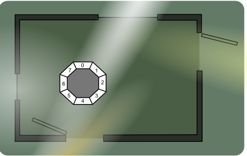
Each room in the house has a unique lighting situation. A simple eye that looks around in eight directions would "see" a pattern of light and dark segments. Each cell is connected to one ADC on your uC.
I actually built this now!
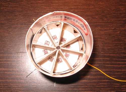
It's made from pbcb and has eight LDRs glued flat onto the floor. The yellow wire is common V+. The blank wires are the individual LDR leads.
Each LDR makes up a voltage divider with a fixed resistor, all of which have the (exact) same value. Here it is soldered to a Mr Basic breadboard.

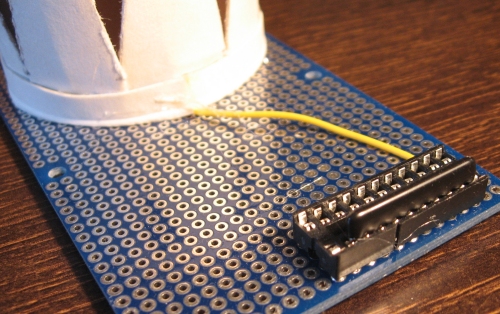
The little black strip in the DIL socket is a SIL resistor network. It holds eight 22kOhm resistors with one common ground. It has nine pins. Here is a schematic of one single divider and the eightfold voltage divider I built.
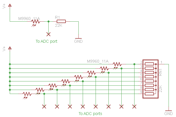
These voltage dividers give a low voltage in the dark and a high voltage in bright conditions. The SIL resistor chip makes it easy to change the values. I experimented with values 2200 Ohm and 33 KOhm before choosing 22 KOhm. Also, the compact SIL package guarantees that the individual resistors all have the exact same value.
The second row of connectors in the socket connects to this Picaxe 40X2 board that you cannot buy anywhere in the world. But is very easy to make yourself. The flatcable also provides V+ and GND to the eye.

The little chip is a 64 KiloByte eeprom that can be written/read through I2C. The potmeter is used as a user input device. I turn it all the way left to make the Picaxe take readings. I turn it all the way right to make it dump the bytes from eeprom to my PC. It actually has two more functions. In either half of the potmeter's arc, is an area that resets the internal address counter.
The current firmware in this eye just records eight byte values every 30 seconds. The memory dump can be captured to file using any terminal emulator (like Putty). I wrote a few programmes in Processing to visualize the data.
This is a part of the raw data represented as a linegraph. Each reading contains eight byte values (0-255). The device registered one reading every 30 seconds. The boring zero-values were removed manually.

The thingy below represents the eye in its physical shape. Each cell in the eye is visualized as a segment of the circle, numbered 0-7. The beige segments indicate actual byte values. Those values are printed along the circle in grey. The red number indicates the highest value or brightest cell.

The purple segments visualize the normalized values. Each value is "stretched" to be a proportional fraction of 255, relative to the brightest value in the series. The brightest in this example is 177. So the other values were Normalized:
N = value * (255 / 177)
The purple segment in the brightest cell is always filled to the edge.
The narrow segments (more saturated in colour) give values in 8 bit resolution. The wider segments (darker in colour) are values in reduced 2 bit resolution. Values 0-255 are reduced to values 0-3.
Each ring indicates one quarter of the full ADC range. The inner ring (filled in black) indicates 0, the next is 63 (or 1), the next is 127 (or 2). The outer ring indicates 191 (or 3).
The large text in the bottom is a binary number compiled by combining eight 2bit values, highest first. The highest normalized value (red) is always binary 11 (3 in human terms). So we might as well discard it. The remaining 14 bits make for the pattern I am really interested in. That could be the memory address where I store the room ID number.
I wrote a Processing "sketch" to visualize all the memory locations where the room number would end up, if I would process all data for a whole day. I set my eye on my dinner table for some 24 hours and let it soak up all the light information as the sun came up and went down again. And when I came home, I switched on the lights and TV, opened and closed a few doors. And all kinds of patterns were collected into the logfile. This is what my proposed algorithm would have memorized.

(All images are actually higher resolution: open them separately for a closer look.)
It would appear that my living room produces quite a few different "fingerprints". Hopefully these do not (all) clash with the fingerprints from other rooms in my house. I must write a programme to investigate how badly the patterns overlap. Only then will I be able to tell how distinctly my device can recognise an individual room or location in my house.