

I want to share a 3D simulation program I have used. Short story, it is not user-friendly but quite powerful.
the programs is named "freeCAD", but it is not the only one using this name. Here is its home http://www.ar-cad.com/freecad/
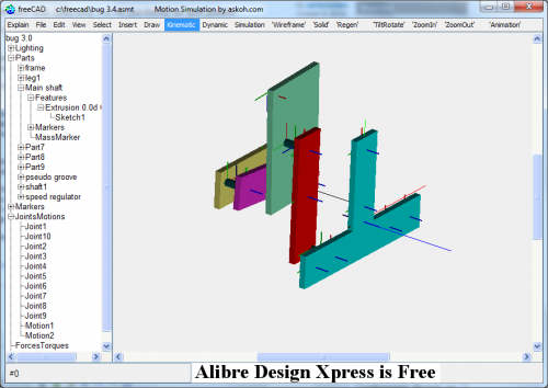
In my design I have two cam wheels that control the movement of a leg. There is a 4-bar mechanism involved. Not all movements are exactly in one plane, so it is a 3D problem.
In order to exactly define the leg movement (constant speed in a straight line for at least 50% of the cycle) I need to reverse-engineer the system.
FreeCAD is terrible to work with. For instance, if you want to add geometry you need to select the root node of the document tree, select a plane from the menu, add a part from the menu. Then select that part in the tree, again select a plane from the menu, add a sketch from the menu and then add a rectangle from the menu and drag in onto the screen. If you miss one step, you get an alert and you can start all over again.
It took me one day to enter the mechanism in the video. And I am not even finished, this part is in fact a 2D problem and could have been done much easier in Linkage.
In my video the red bar is actuated by the cam wheel, which in turn is driven by a gear motor. The top left corner of the green rectangle is connected to the leg. Meanwhile, the yellow bar at the back (moving slowly) regulates the leverage of the system. When the yellow bar is rotated to the left, the green and red elements almost move as one element, but when the yellow bar is rotated to the right the green rectangle moves much more aggressive.
The yellow bar also regulates the mechanism at the other side (not in the video), which means that if one leg goes slow, the opposite one goes fast. This will make it possible to steer the robot.
https://www.youtube.com/watch?v=a4kRy1a0_uU
https://www.youtube.com/watch?v=a4kRy1a0_uU