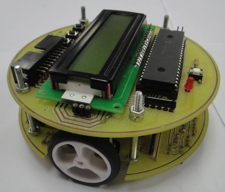
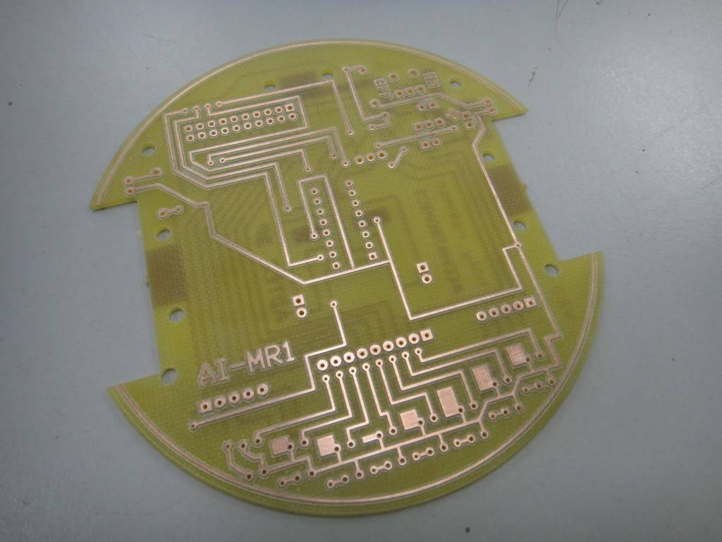
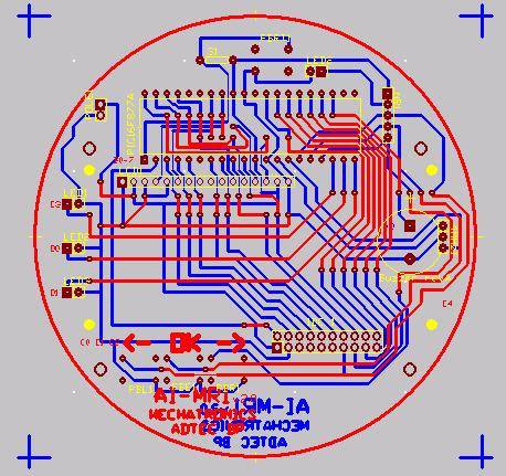
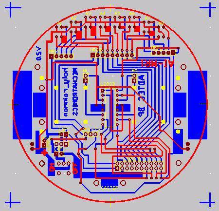
Project Description: To implement classic PID control algorithm to the Line Following Robot using Basic Language. The sensors used are from CYTRON SN-IRS-02 (thanks for the cute sensor) and are processed using analogue method. The motor driver used are L293D + micrometal gearmotor 30:1 which are common in mobile robot . I made the PCB board stacked together cause it gives a compact image towards the robot. I put on a common LCD to scroll the menu and to ease the troubleshooting process. The hardware cost around RM 250. The robot from the video are a bit sluggish cause the optimum pid value was not tuned at that time. Need a bit tuning, tweeking and some trial and error to obtain the correct value.
thanks, it took me a while to get that perfect shape. but i mainly use DIP package which is bulky. If only i had knew a shop selling soic or tsop packege at my local area…
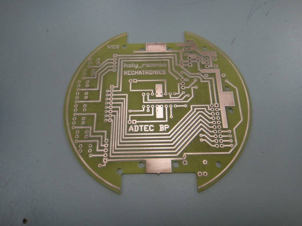
look like you etched them yourself/yourselves. I do notice the nubs at the wheel cut outs. Where the boards etched then shaped or shaped then etched?
The nice thing about using a plain PIC and programming it outside the chip is that you are free to use whatever language catches your eye. Rather than if you had used the PICAXE and could really only program it with their version of BASIC.
I would have liked to see the positive effect of your PID algorithm. More to the point, I would have liked to see a run w/o PID and then with. Maybe even higher speed if possible.
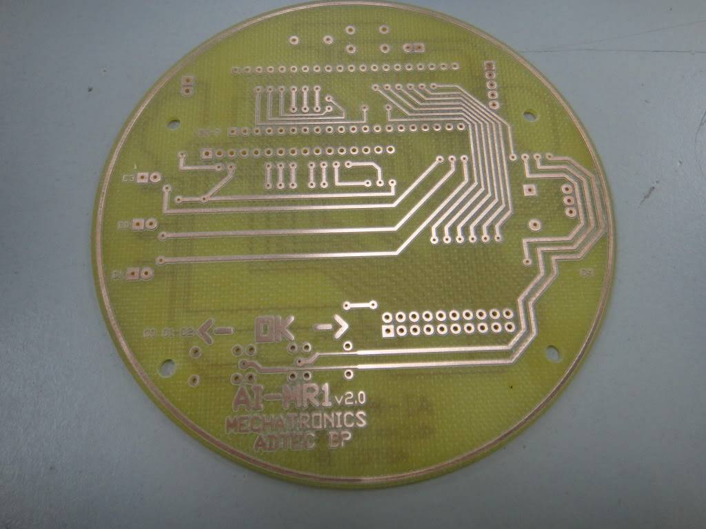
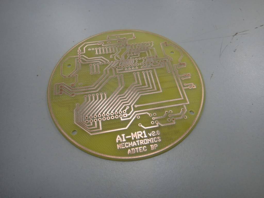
wll birdmun, i didm’t etched it, i use cnc machine specifically LPKF protomat s62. a very cool machine to fabricate a pcb. you can say it is not a home made but a lab-made cause i did it at my working place.
though now many hobbyist are moving towards arduino based, i like myine the old school way.
if i have some free time, i’ll try to make a video to differentiate the with and w/o pid algorithm. actually i have to work on the damping factor in the algorithm as well rather than focusing on the tuning process. it would take soem time but the pleasure is wordless.