A quick search here did not give me any relevant hits. So, I was hoping to ask the electronic gurus here if my plan/idea will work.
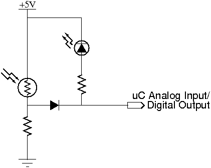
My thinking is that the photoresistor will be able to be read by the analog input and, because of the diode, the LED will not light unless the microcontroller is set as an output and set LOW.
EDIT:
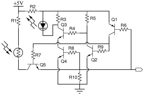
Based on the input so far, I have redrawn the circuit. I hope the collective doesn't mind helping me get circuits straight.
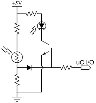
The transistor was added to keep the LED from being part of the analog in circuit. The resistor inline with the pin was added for current protection and the one above the LDR was added for similar current protection, but, can be removed if need be.
LAST CHANCE:
If this doesn't pass muster I will stop bugging the group on this.

The tri-state section, Q1, Q2, R5, R6, R9, R10, is lifted from nuumio’s tri-stating motor control. The NAND gate, Q3, Q4, R3, R4, R8, is from this site.
I don’t see any obvious short circuit paths, but, then again this is getting pretty convoluted to just look at.
Why don’t you just try it?
Why don’t you just try it? If you are afraid it might ruin your uc you can use a multimetre to check first.
To be brutally honest
I have not tried it because I have as yet to get a LED to flash. The problem is at the moment that I don’t understand why the LED isn’t flashing. My next attempt may be to cause the whole port to cycle and see if the LED will flash properly on any pin.
I don’t see anything in the schematic that would cause damage to the uC. So, that is not a fear either. 
In the case of the schematic above
you are 100% correct. In the case of the problems I am having, the above schematic has no hold and the LED is indeed oriented correctly. I promise.
False positive
Well the only thing I can see wrong with this is that the LED/Resistor will give a false positive voltage on the input when our are using the input as analog input.
Warning
the second problem that can occour is when the pin is set to output mode with a low ouput and the ldr has a very low ruesistance the current can get higher than desired. possible damage the ldr or outpu
should work
I would move the resistor that is below the LED next to the uC pin.
That would make sure that current flows through the LED even if the LDR has low resistance. It also protects your uC from sinking too much current.