I'm having a lot of problems with the servos I'm using to build a quadruped robot. I should start by mentioning that I bought the servos from Dagu like 4 years ago, BUT most of them had never even been unpacked until recently.
The problems are the following:
(1) Some of them make clicking noises when being turned beyond a certain point. It sounds like they are trying to turn beyond their max. capability, even though they are well within the normal range (eg. 30-40 degrees).
(2) Before putting together the bot I tested them all and set them to 90 degrees, but yesterday when I started programming a lot of them had moved so that I had to set them as low as 75 or as high as 115 to get a 90 degree angle. And generally they seem rather inconsistent with the angles. Meaning that I have to use very different values to get equivalent angles in the different servos.
(3) I'm also getting quite a bit of noise and jitter from them. Some of them sometimes even sound as if they are working beyond their limit, even though they may be at 90 degrees without carrying any weight.
(4) Whenever I upload a new Arduino sketch and start up, the legs of the bot goes totally spastic, but perhaps this is normal?
(5) Ah and one was working just fine for quite a while and then suddenly stopped. Now it doesn't move at all.
I have noticed that some folks use resistors on the signal wire, from the Arduino to the servos. Apparently to protect the servos. Could doing this possibly solve some of the issues?
I also know a lot of folks use caps to sort of normalize the current flow in servo circuits. Again could this solve some of the problems? I was under the impression that this was more of an issue when using batteries, and currently I'm using a PC power supply, which supplies a very steady 5V and plenty of Watts.
Anyhoo, all input from you guys is very welcome. If some of the issues could be solved it would be great. But even if not I'd like to atleast understand what is going on.
UPDATE:
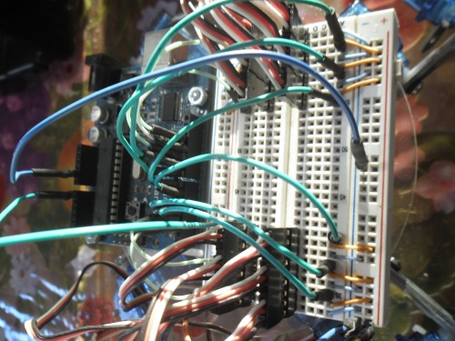
Here is a pic of the circuit...
I can’t offer any easy
I can’t offer any easy answers, especially about the mechanical defects of the servos, but I had some very weird behaving servos when they were underpowered. 12 servos are going to draw 200-250mA at 5V each, especially when stalled – that’s 2-3A current, with additional spikes when they start. Most power sources wouldn’t handle that, and their voltage would drop rapidly – often resetting the logic board in the process, but also resulting in weird behavior of the servos. Adding a large (1000µF) capacitor helped for the spikes, but I still had problems until I just got a battery with low enough internal resistance, so it can provide enough current for the servos (20C in my case).
As for the positions of the horns – I always drill holes to have easy access to the horn screws, and adjust them with the servos on and set to 1500µs pulse width. The horn’s teeth inside are assymetric, so you can’t always get them to be exactly level – that’s what I have trimming in software, basically an array of values to add to the servo position whenever we are setting it. But it’s never more than 200-300µs (for a 180° servo that would be 2-3°).
Oh, you can open them and look for broken off teeth and such. Just make sure to not lose any parts.
By the way, you really want
By the way, you really want to drive them in microseconds of the pulse width, not in degrees – the resolution of 1 degree is too low to have smooth movements.
As promised I took a better
As promised I took a better foto in daylight. I added it to the topic description…
OK to sum it up a bit I
OK to sum it up a bit I apparently have som power problems. For starters I sholdn’t be cascading 12 servos on a breadboard.
So I’m gonna solder up a circuit for supplying the servos. I’m thinking perhaps 2 separate circuits each supplying 6 servos. Each with a 5V (both input and output) voltage regulator up to 3A. Does that sound reasonable? If so can anyone recommend specific type of regulator and a setup/circuit that would be appropriate to my needs? (I noticed after googling a bit that these things seem to requiere other components to work)
Also I’d like some suggestions on which caps to use and how/where. Eg. is it OK just to put one large cap for the whole circuit, or is it better to put several smaller ones?
Besides, I’m pretty convinced that not ALL of the problems are due to power issues. What a about (1) and (2)? They are actually the worst problems.
Anyhoo thanks a bunch for all your input guys…
As for (1) and (2), you
As for (1) and (2), you could open the gear boxes and see if all the gears have all the teeth. It’s common for the plastic servos to get “stripped” – have some of the teeth broken off due to trying to rotate them manually, or too high force put on them.
You might also be going out of their range. Remember, that the range of the servo is counted from 90° up and down, not from 0. The Arduino Servo library assumes 180° range and converts the 0° to 90-90° and the 180° to 90+90°. That may be too far for your servos. Try going from 20° to 160° or such, see at which point the start having problems.
I’m betting on the problems with range, plus missing teeth in some of them due to constantly forcing them out of range.
OK I’ll try opening a servo
OK I’ll try opening a servo to see what is going on. I’ll have to buy a smaller screwdriver first though, cause the ones I have are way too large. These screws are just tiny.
And like I said I’ve been using the standard Arduino library write-function which takes an angle between 0 and 180. When I do write(90) they are all fine, but some of them showed problems allready at write write(30) or write(40) for example, which I believe they shouldn’t.
And I’m not sure what you mean by “due to constantly forcing them out of range”? Like I mentioned most servos, allthough a couple of years old, have never been used. 10 of them were still in their small bags inside a larger sealed bag until a few days ago.
The original "official"
The original “official” servo range is 90°, so they would be fine from 45° to 135° using the Servo library. Of course most servos allow much more, and there are even servos that are officially sold as 180°. But in the RC model usage they rarely go beyond the 90° (they usually just push a rod), so that’s the only sure thing. You could try moving them by hand (very carefully, easy to strip them this way) to determine where they stop.
Anyways, I can keep on guessing until the cows come home, it won’t help you at all, you just have to check for yourself.
Ok I had no idea that the
Ok I had no idea that the “official” range is only 90°. I always thought it was 180°, and it also seems to be the assumption by many others, judging by what I’ve read here and there on the internet. Eg. in the description of the Arduino servo library it says: “Standard servos allow the shaft to be positioned at various angles, usually between 0 and 180 degrees.”.
I’ve also previously used servos in their full 180° range without problems, but I can’t recall if I’ve done it with these particular servos.
And yeah I am, as I said, gonna try and open one up to see if that will make me any wiser, allthough I doubt I will be able to determine much given that I don’t know what to look for (except perhaps broken teeth on the gears).
Anyhoo thanks for the info on the servos…
The key word here is
The key word here is “usually”. Practically all servos need to support the 90° plus some margin on either side. There is usually no reason to not make it full 180° or even more, if the pot has that range, but it can vary greatly, even with the same model of servo, with cheap servos. Of course, the more expensive ones will be more consistent, etc.
I hate that they never document the ranges and the corresponding pulse widths.
CAPS!
OK I’ve decided not to think about a voltage regulator for now. What I will do is solder a board so that the current for powering all the servos doesn’t flow through the breadboard. I also wanna put on some caps to deal with surges, spikes, noise, etc.
I understand that you can use caps both on the main wire that powers several or all the servos, as well as caps for each individual servo. What I really need now is therefore advice on the caps (setup and sizes). That way I can buy the stuff tomorrow (saturday) and get busy in the weekend.
I’m thinking the following: I’ll make two circuits, each for powering 6 servos. Each will have one large (electrolytic) cap on the main wire, plus a smaller (ceramic) cap for each servo.
Does this sound reasonable? If so what sizes of caps would you guys recommend? (remember we’re talking 8g servos powered by an AT supply at 5V)
Hmm … unfortunately no
Hmm … unfortunately no answers yet 
Well for now (after quite a bit of research) I’m thinking 1000 uF caps for the main wires and 10 uF caps for each servo. Does that sound completely off?
You want to mix electrolytic
You want to mix electrolytic capacitors with normal (monolythic?) ones, becase the electrolythic ones have a large inertia. That’s why you can usually see two capacitors side by side, one big and one large – the big one will smoothen out the large changes, the small one the remaining noise (for example, here https://www.robotshop.com/letsmakerobots/once-youve-decided-batteries-how-do-you-regulate-voltage).
I’m not saying you need a pair of them everywhere, but I would put smaller, but non-electrolythic caps on the servos.
It’s hard to say what sizes you need without actually measuring your noise, though.


