One for TofuRobot.
1. The electronics:-
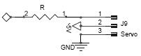
The Diamond on the left is the Picaxe pin, I normally use a resistor 100-200R just to protect the Micro just incase of short or plugging the servo in backwards (there are two types of people using servos, those who have plugged servos in backwards and those who are about too!).
Pin 1 is the signall and on the servo it will be Yellow or someing like that, 2 is the power between 4.8-6Volts is ok, it is often red, and the last (3) is ground and is normally black.
2. The Code
The PICAXE-08 Lacks the servo function in the language so we are going to need to do this by hand.
The first thing you need is an outside loop of between 18 and 25ms, the actual time is not all that critical, the servos will jitter if too long.
The position of the servo is set using Pulse Width Modulation, the pulse is between 1ms and 2ms and the width of the pulse sets the position.
The PICAXE-08 does have a pulsout function which takes two parameters:
pulsout pin, duration
here is the info from the Pixaxe manual
Information:
The pulsout command generates a pulse of length time. If the output is initially low, the pulse will be high, and vice versa. This command automatically configures the pin as an output, but for reliable operation on 8 pin PICAXE you should ensure this pin is an output before using the command.
Restrictions: The 14M only supports pulsout on outputs 0,1,2.
Affect of Increased Clock Speed:
4MHz 10us unit
8MHz 5us unit
16MHz 2.5us unit
So the code is going to look like so:
main: `this is our outside loop
pulsout 1,150 ‘ send a 1.50ms pulse out of pin 1
`other servos.......
`your code.....
pause 20 ‘ pause 20 ms
goto main ‘ loop back to start
Now the caveats! ther are a few.
a. Outside loop time is governed by our code, you will have to adjust the pause duration to keep the loop time between 18-25ms
b. Loop time is set also by the pulse duration of the pulsout command, I dont think it returns until the pulse is over.
c. Debugging, single stepping is not going to work well ;-)
I hope that helps
Cliff
i don’t get what you mean
i don’t get what you mean pulse with modulations sets the potition. I tried changing the number after the pulsout and the pause time but all my servo does is go all the way to the left and then starts jittering cause it’s reached it;s max left
Ok this is getting more
Ok this is getting more strange. I looked up PWM and still. i changed every number varrible and the same thing happens. servo turns all the way to the left. Could you provide a sameple program like. servo all the way left then center then all the way right.
Servo control
Hi Tofu,
to start with the servo needs a pulse train like shown in the top line below, about between 18 and 25ms the servo should receive a pulse, if the pulse rate is too slow this triggers the servo’s missing pulse and it will slew to one stop, if you send the pulses much too slow it will jitter away very badly, your problem might be the pulse rate is too slow. Too fast can also be a problem.
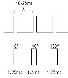
The servo's posistion is governed by the width of the pulse (time), about 1.25ms will be the servo disk at 0degrees, 1.5 about in the middle and 1.75 around 180degrees or there abouts. So to get a servo to slew to say 105 degrees you need to out put a POSITIVELY going pulse which lasts about 1.55ms every ~20ms. The code would something like this
main:
low 1
pulsout 1, 155
`your cother code, ie robot stuff.....
pause 19 ‘ pause 19 ms
goto main ‘ loop back to start
One thing to remember, it the pulsout 1, 155, should be a low/high/low pulse so we need to make sure the pin is low before calling pulsout.
The one is the Pin number, the 155 is the time in microseconds x 10 (4Mhz clock!) (i.e. 1.55ms if my maths are ok) this sets the position of the servo.
the pause 19 sets the delay and in effect will set the interval between the pulses, this should decrease as the pulse increases and like wise as you add code.
best regards
Cliff
Thanks. This is good stuff.
Thanks. This is good stuff. I;m going to go program my chip now!
Servo’s good luck, let me know how you go.
Just a couple of tips.
The signal to the servos should alway be less <= to the supply voltage,
Becareful if you are using a single supply, they can draw a lot of current and push your voltage reg in to crowbar or brownout resetting the processor.
If you have a CRO it would be worth haveing a look at the signal, just to be sure to be sure!
as we say downunder 'ave a gud weekend!
Pulse rate
I’ve actually had better performance out of some of the servos used when pulsing them at a higher rate than normal. The micro used, an IsoPod, had firmware that allowed only a minimum of 13 ms between pulses from certain pins. At this rate the servos appear quicker in response as well as stronger in holding torque.
I don’t recall experiments at a faster rate than this, but all the servos tried at this rate worked well.
One device that did experience malfunction was a digital speed control designed to operate from a servo signal.


